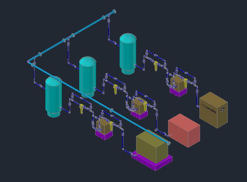
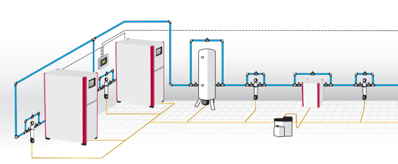
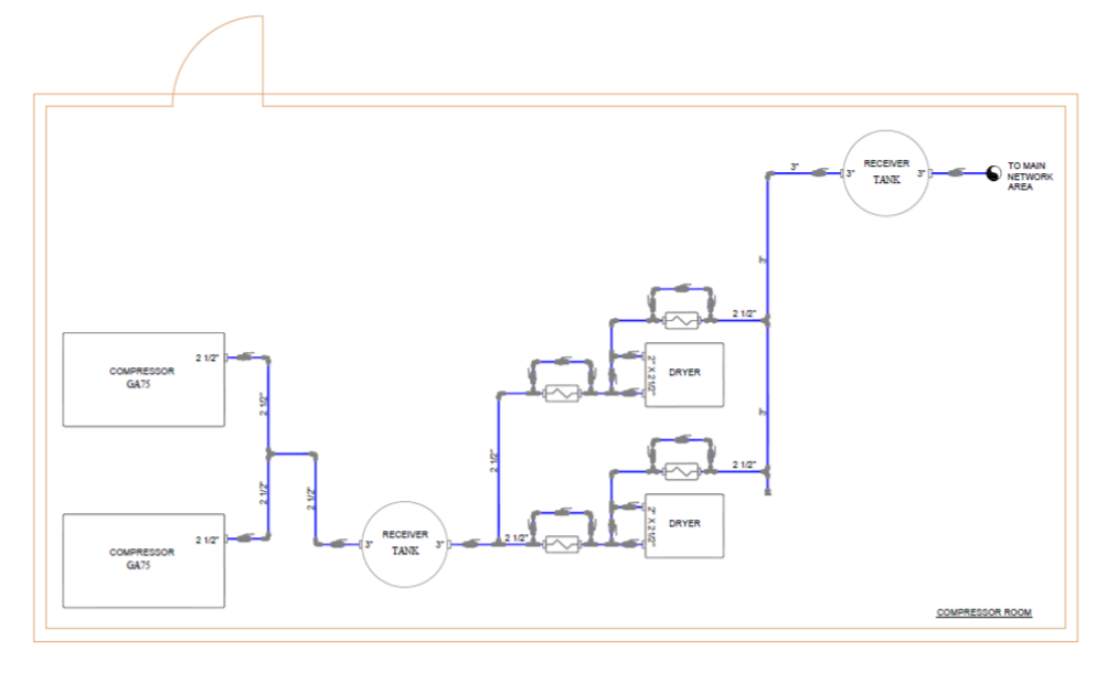
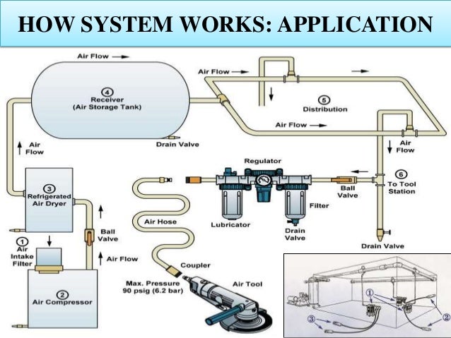
37 compressed air system piping diagram
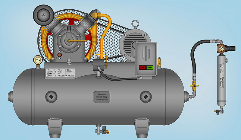
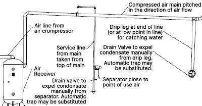
The purpose of compressed air piping systems is simple: to deliver compressed air to where it is needed. However, designing a compressed air system is more difficult than you might imagine — the compressed air has to be delivered with sufficient volume, good enough quality and enough pressure to power the components that require compressed air. Best Practices and Tips for Compressed Air Piping Systems A brief synopsis of “Section 3, Distribution System” from Best Practices for Compressed Air Systems follows. This 325-page book is available at our bookstore. Pressure losses due to inadequate piping will result in increased energy costs and variations
14.11.2015 · This compressed air is then supplied to the system through a series of pipes and valves. The word ‘Pneuma’ means air. Pneumatics is all about using compressed air to do the work. Compressed air is the air from the atmosphere which is reduced in volume by compression thus increasing its pressure. It is used as a working medium normally at a ...

Compressed air system piping diagram
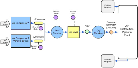
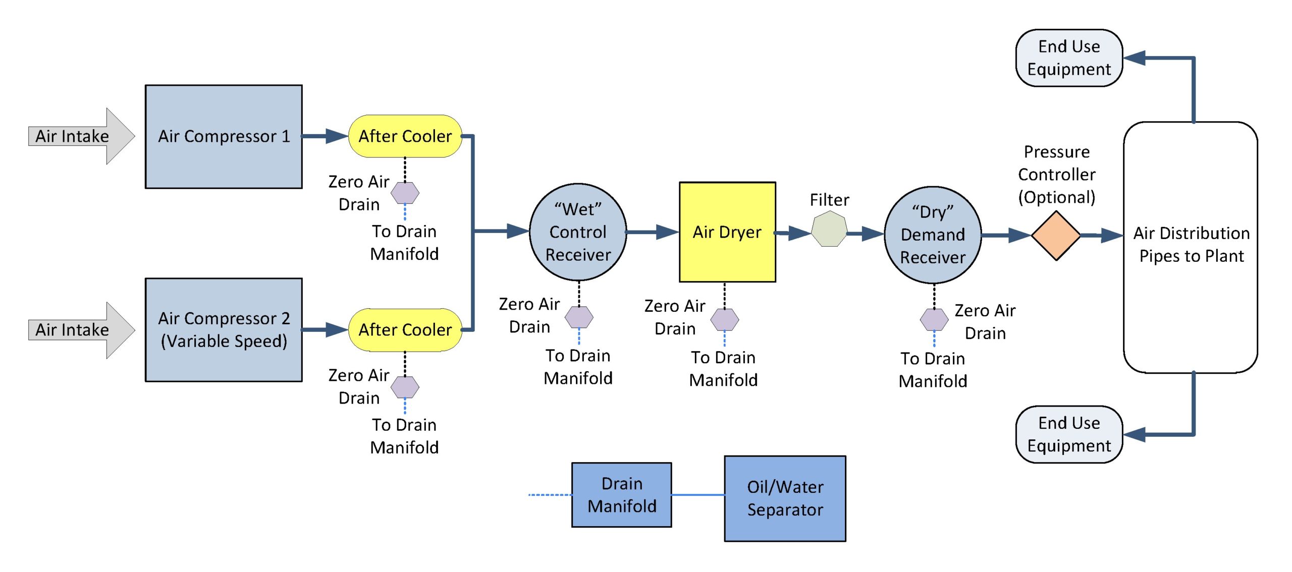
A Process Flow Diagram - PFD - (or System Flow Diagram - SFD) shows the relations between major components in a system. PFD also tabulate process design values for components in different operating modes, typical minimum, normal and maximum. A PFD does not show minor components, piping systems, piping ratings and designations. 12 May 2021 — About Compressed Air Piping Systems ... Your compressed air distribution system consists of a series of pipes that convey compressed air from the ... A common air piping design error which compressor line engineers make is selecting flow lines which are too small to handle the amount of pressure generated by ...
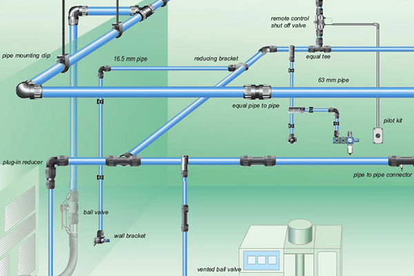
Compressed air system piping diagram. General Rules of Air Compressor Piping Diagrams. Piping is a very important component when it comes to designing and developing a successful air compressor system. As compressed air faces a risk of losing pressure across the system (pressure drop), or even contamination along its path. This unit is the piping, glue that holds this intricate system together. Unfortunately, setting-up seems rather easier said, than done. Various aspects need to ...Air Compressor Piping System. · Environmental Condition. · Angles. · Pipes. Compressed Air System Standard Piping Diagram Author: Department of Veterans Affairs, Office of Acquisition Logistics and Construction, Office of Construction and Facilities Management, Office of Facilities Planning, Facilities Standards Service Subject: Standard Detail Created Date: 10/26/2017 1:02:30 PM Air System Piping. AIRnet is an advanced piping system that offers ease of installation, reliable performance, and substantial energy savings over traditional piping materials. Total cost of ownership is dramatically less expensive than traditional systems where leaks and corrosion over time can impact system efficiency, air quality, and system ...
17 Sep 2021 — THE PIPING SYSTEM AND COMPRESSED AIR · Piping Layout Considerations · Types of Piping Material · Talk to the Compressed Air Piping Experts. Compressed Air Basics – Piping. February 23, 2018. Your air compressor is the heart of your air system. Most customers focus on the compressor and consider the piping as a secondary concern. However, just like a heart can fail because of clogged arteries, a compressor can fail because of improper piping. You have many different options on the ... The compressed air leaving the compressor should be properly prepared before it goes into the circuit. The air should have the proper operating pressure for the circuit. The improper fluctuating pressure level in the piping system can adversely affect the operating characteristics of the system components such as valves, cylinders, etc ... AIR SYSTEM PIPING DIAGRAMS 121 Trailer Air Systems Tandem Axle Trailer (Spring Brake Priority 110500 or 110800 / Service Reservoir Priority 110700) Tandem Axle Trailer (Protected Reservoir System) Phone (602) 253-1007 Page 72 Fax (800) 222-2334 AIR SYSTEM PIPING DIAGRAMS 121 Trailer Air Systems Single Axle Trailer (Double) (Spring Brake ...
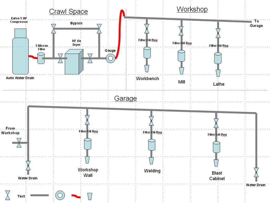
Shop Air Piping Layout Diagrams. As we all know, compressed air is a key element in everything we do in the shop. And the quality of the paint job on ... Compressed Air System Design Efficient Compressed Air Systems When a compressed air system is properly designed, installed, operated and main-tained, it is a major source of efficient industrial power, possessing many inherent advantages. Compressed air is safe, economical, adaptable, easily transmitted, and provides labor saving power. Will your air system support the manufacturing process at this pressure? If not, the first order of business should be to develop a generic piping schematic ... Pressure test flow diagram shall be prepared by Construction Contractor. These diagrams shall show the system to be tested, the valves to be opened, and the equipment to be blanked with blind flanges and necessary instrumentation. 4.2. BLIND FLANGES AND BLANKS - Pressure Test of Piping System. 4.2.1. Where the piping system is required to be disconnected from equipment in the test ...
Make a Diagram of the Piping System. Make a diagram where the system is structured with nodes as shown below. In the very simply circulating system used in this example the first node (0) is the pump. The next node is the tees (2) where the piping system splits up. The other nodes are the heating radiators. In many systems the structure can be simplified as above since the piping in both ...
eCompressedair offers a comprehensive range of Aftermarket Parts & Kits for Ingersoll Rand Compressors. All of our aftermarket replacement compressor kits and parts meet or exceed the original OEM specifications. Buy Now!

Simpair Sistem Perpipaan Apersoll Jonathan Instalasi Perpipaan Udara Terkompresi Buy Simplair Evolution Amp El Tekanan Tinggi Pipa Simpair Sistem Perpipaan Easyline El Kompresor Pipa Simplair Modular Piping System Simplair Epl Pipa Sistem Kerja
eCompressedair offers a comprehensive range of Search for Kaeser Compressor Parts by Part Number. All of our aftermarket replacement compressor kits and parts meet or exceed the original OEM specifications. Buy Now!
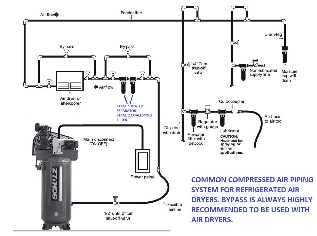
Reduce the moisture within your air compressor piping diagrams by changing the supply inlet. This helps because water is heavier than air and drops to the bottom of the tank. Taking air from the top of a compressor means that the amount of moisture taken with it too is reduced. We also recommend that you have an aftercooler fitted with your ...
The purge air from the compressed air system can be eliminated if a blower is used for the circulation of heated atmospheric air through the desiccant bed. To protect the desiccant bed from oil contamination from the air compressor, a coalescing filter is required upstream of the dryer. To protect downstream equipment from desiccant dust or “fines”, a particulate filter downstream of the ...
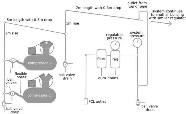
Air Piping Layout Shop Air Piping Layout Diagrams . As we all know, compressed air is a key element in everything we do in the shop. And the quality of the paint job on refinishing work is affected by the quality of the compressed air we use. The quality of our compressed air is also effected by how our air delivery lines are laid out in our shops.
3.2.2 Water vapor in compressed air 72 3.2.3 Oil in compressed air 73 3.2.4 Micro-organisms in compressed air 74 74 3.2.6 After-cooler 75 3.2.7 Water separator 75 3.2.8 Oil / water separation 75 3.2.9 Medical air 76 3.3 COOLING SYSTEM 77 3.3.1 Water-cooled compressors 77 3.3.1.1 General 77 3.3.1.2 Open system without circulating water 77
25 Aug 2019 — An air compressor piping diagram is created by connecting an air compressor to any end-user tool through the use of a pipe.
Document the current compressed air system in place. Include the type of compressor (oil-free, oil lubricated); type of system filtration for particle, water and oil removal; storage tank capacity; type of point-of-use filters; and material used for distribution piping (stainless steel, copper, aluminum, galvanized, etc.). Include make, model, serial, and part numbers. This information will ...
A common air piping design error which compressor line engineers make is selecting flow lines which are too small to handle the amount of pressure generated by ...
12 May 2021 — About Compressed Air Piping Systems ... Your compressed air distribution system consists of a series of pipes that convey compressed air from the ...
A Process Flow Diagram - PFD - (or System Flow Diagram - SFD) shows the relations between major components in a system. PFD also tabulate process design values for components in different operating modes, typical minimum, normal and maximum. A PFD does not show minor components, piping systems, piping ratings and designations.












0 Response to "37 compressed air system piping diagram"
Post a Comment