38 boost converter circuit diagram
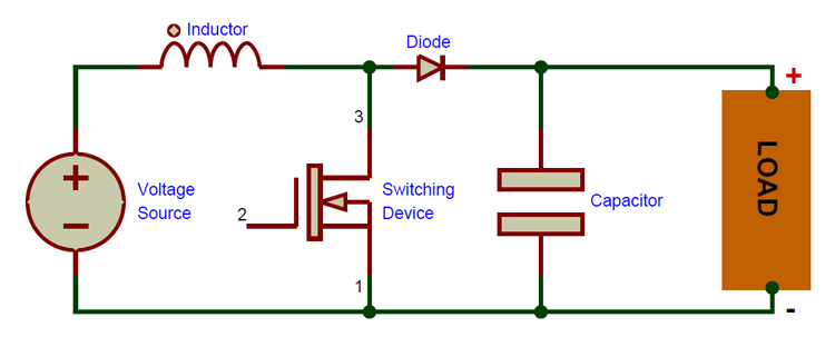
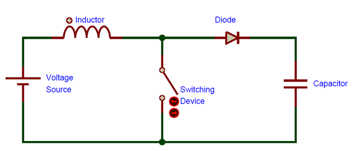
Based on the circuit topology, CBC converters can be classified as bridge boost converters (BBC), semi-bridgeless boost converters (SBBC), and bridgeless boost converters (BLBC). The 'best' topology selection involves tradeoffs between power handling capability, efficiency, complexity, THD requirements, and other performance considerations. Fig. 3.2.1 illustrates the basic circuit of a Boost converter. However, in this example the switching transistor is a power MOSFET, both Bipolar power ...
"an aid, a boost," 1837, from leg (n.) + up (adv.).

Boost converter circuit diagram
The Ćuk converter (pronounced chook; sometimes incorrectly spelled Cuk, Čuk or Cúk) is a type of buck-boost converter with zero ripple current. Ćuk converter can be seen as a combination of boost converter and buck converter, having one switching device and a mutual capacitor, to couple the energy.. Similar to the buck-boost converter with inverting topology, the output voltage of non ... EDIT: Problem 1 was the diodes. Now, the circuit works for low-power applications. Major downside being that I need it to work at 2A. I think it's because my layout is not good for high frequency stuff, but the MT3608 has a low-power, low-frequency mode. Once I jump into the full 1.2MHz setup, things go awry. I'm trying to build a boost converter out of [this MT3608 chip](https://www.olimex.com/Products/Breadboarding/BB-PWR-3608/resources/MT3608.pdf). But I'm not having any luck. I'm not sure w... A look into how boost converters work in a very visual format. try this circuit: goo.gl nkhq9hboost converter wiki: en. .org wiki boos. Boost converters (dc dc step up) electronics intermediate 1 simply electronics converter vs inverter difference between converter and inverter learning engineering type a chopper, type b chopper, type c chopper, type d chopper, type e chopper working ...
Boost converter circuit diagram. Nov 29, 2019 · 3 Phase Inverter Working . Now let us look into the 3 Phase Inverter Circuit and its ideal simplified form.. Below is a three-phase inverter circuit diagram designed using thyristors & diode (for voltage spike protection). And below is a three-phase inverter circuit diagram designed using only switches. As you can see this six mechanical switch setup is more useful in understanding the 3 phase ... "to lift or raise by pushing from behind," 1815, literal and figurative, American English, of unknown origin. Related: Boosted; boosting. As a noun, "a lift, a shove up, an upward push," by 1825. [List acquired here.](https://github.com/first20hours/google-10000-english) a aa aaa aaron ab abandoned abc aberdeen abilities ability able aboriginal abortion about above abraham abroad abs absence absent absolute absolutely absorption abstract abstracts abu abuse ac academic academics academy acc accent accept acceptable acceptance accepted accepting accepts access accessed accessibility accessible accessing accessories accessory accident accidents accommodate accommodation accommodations acc... a aa aaa aaron ab abandoned abc aberdeen abilities ability able aboriginal abortion about above abraham abroad abs absence absent absolute absolutely absorption abstract abstracts abu abuse ac academic academics academy acc accent accept acceptable acceptance accepted accepting accepts access accessed accessibility accessible accessing accessories accessory accident accidents accommodate accommodation accommodations accompanied accompanying accomplish accomplished accordance according accordingl...
1610s, "an illustrative figure giving only the outlines or general scheme of the object;" 1640s in geometry, "a drawing for the purpose of demonstrating the properties of a figure;" from French diagramme, from Latin diagramma "a scale, a musical scale," from Greek diagramma "geometric figure, that which is marked out by lines," from diagraphein "mark out by lines, delineate," from dia "across, through" (see dia-) + graphein "write, mark, draw" (see -graphy). Related: Diagrammatic; diagrammatically. The verb, "to draw or put in the form of a diagram," is by 1822, from the noun. Related: Diagrammed; diagramming. Hi all, I recently bought [this](https://uk.banggood.com/DC10-60V-30A-1500W-To-12-90V-Boost-Converter-Step-Up-Power-Supply-Module-p-1076169.html?cur_warehouse=CZ) boost converter for a project and it has arrived broken. :/ The trimmer potentiometer with the markings W104 and T 110, marked as the "Low Battery Protection Adjustment 8-50v" has sheared off of the board and I wish to replace it. Can anyone help me identify the exact component so I can buy another? Secondly, does anyone know where ... 1530s, "one who makes converts," agent noun from convert (v.). Meaning "appliance that changes materials from one shape or condition to another" is from 1867. a aa aaa aaron ab abandoned abc aberdeen abilities ability able aboriginal abortion about above abraham abroad abs absence absent absolute absolutely absorption abstract abstracts abu abuse ac academic academics academy acc accent accept acceptable acceptance accepted accepting accepts access accessed accessibility accessible accessing accessories accessory accident accidents accommodate accommodation accommodations accompanied accompanying accomplish accomplished accordance according accordingl...
The above schematic is a generalized non-inverting boost converter; it is called a non-inverting boost converter because its input and output ...May 13, 2020 · Uploaded by Electronics Project Hub So, I know I'm taking the long way around on this one, and what I'm doing can probably be done with a couple 555 timers and some components, but I am trying to make a blinker circuit for an old moped. I have a double pole rocker switch wired as the input to some digital read pins, and the output pins go each to some small LEDs as tell-tales, each in parallel with the main blinkers (made from truck side markers) that are wired with boost converters to ramp up the voltage to 12V. The whole shebang... Cadence Design Systems, Inc. is a leading provider of EDA technologies and solutions for semiconductor and systems companies, offering the broadest, most integrated end-to-end solution to help today's electronic designers do their best work when creating tomorrow's products for silicon design creation, simulation, implementation and signoff of analog and digital circuits; off-the-shelf ... May 02, 2016 · Circuit Diagram Of Smps Power Supply Fly-Back Converter The unregulated input-voltage with a constant value is converted into a required output voltage by fast switching with the help of a ‘MOSFET’; the switching frequency is around 100 kHz.
Boost Converter Wikipedia
Crypto APIs, a Bulgarian crypto software company, today has launched a new Wallet as a Service . The service utilizes advanced Multi-Party Computation (MPC) cryptographic key mana
What Is Boost Converter Basics Working Operation Design Of Dc Boost Converters
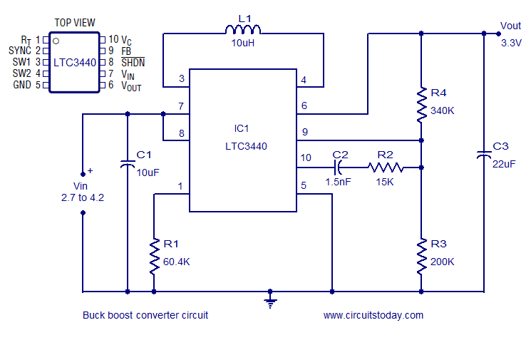
Thus, this is all about the Buck Boost Converter Circuit Working and applications. The information given in the article is the basic concept of buck boost converters. If you have any queries regarding this concept or to implement electrical engineering projects , please comment in the comment section below.
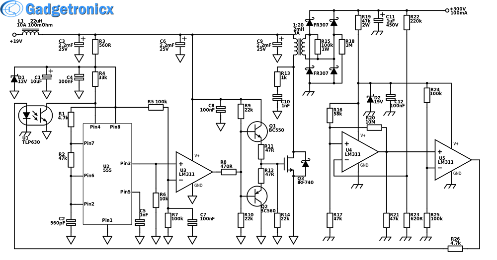
High Power Boost Converter Circuit Diagram Gadgetronicx
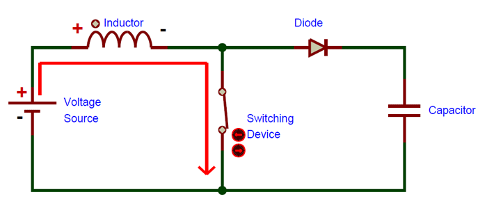
Mar 12, 2020 · A boost converter (step-up converter) is a DC-to-DC power converter that steps up voltage (while stepping down current) from its input (supply) to its output (load).It is a class of switched-mode power supply (SMPS) containing at least two semiconductors (a diode and a transistor) and at least one energy storage element: a capacitor, inductor, or the two in combination.

How Boost Converter Circuit Works Welcome
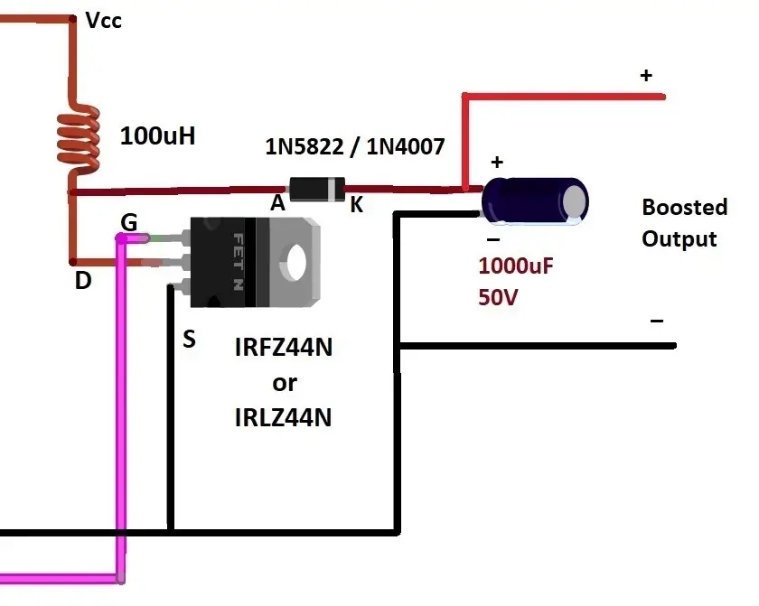
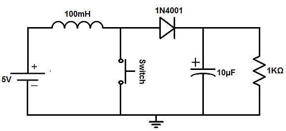
Aug 27, 2020 · This circuit is called a Boost converter circuit. The primary circuit is shown in Figure 1. Basic of DC boost converter. According to the primary circuit, when the switch (S) Closed cause a voltage drop across L or Caused VL is an input power supply (Vin) has current at a coil, The rate of increase of the current is linear.

Tl494 Adjustable Switch Mode Power Supply Universal Buck Boost Converter 1 50v Switched Mode Power Supply Power Supply Power
I have a 3V --> 5V boost converter I want to draw into my circuit diagram, but I don't know the proper symbol. I could make something up, of course, but if there's a standard symbol I want to use it. Thanks. **UPDATE** Thanks for the suggestions. I was under the impression that symbols were standardized for everything. I guess there are just too many conceivable components and devices for that to be true. This converter is just a piece of the device I'm making. I have a 3V button cell ...
Buck Boost Converter Circuit Under Repository Circuits 22339 Next Gr
Hi all, I'm looking at using a boost converter in a project. Either this [one](https://au.banggood.com/1500W-30A-DC-DC-Boost-Converter-Step-Up-Power-Supply-Module-Constant-Current-p-1087084.html?gpla=1&gmcCountry=AU&currency=AUD&createTmp=1&utm_source=googleshopping&utm_medium=cpc_bgcs&utm_content=frank&utm_campaign=frank-ssc-aug-al&cur_warehouse=CN) or [similar](https://au.banggood.com/1200W-20A-DC-Converter-Boost-Step-Up-Power-Supply-Module-Input-10-60V-Output-...

The Dc Dc Boost Converter Power Supply Design Tutorial Section 5 1 Power Electronics News
Jan 7, 2019 — A boost converter is one of the simplest types of switch mode converter. As the name suggests, it takes an input voltage and boosts or ...
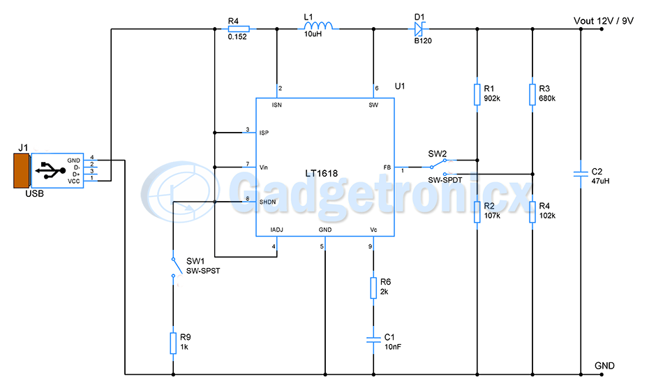
Usb To 12v 9v Buck Boost Converter Circuit Gadgetronicx
影视化妆最新章节免费阅读_影视化妆最新章节列表 影视化妆最新章节免费阅读_影视化妆最新章节列表 ,亚洲阿v天堂无码z2019 ...

Boost Converter Circuit For Solar Cells
Strategic Acquisition Delivers Full Suite of Solutions and Services to Golf Courses and Clubs Featured Image for foreUP Featured Image for foreUP PLEASANT GROVE, Utah, Nov. 17, 2021 (GLOBE NEWSWIRE) -- foreUP, the leading provider of cloud-based, operational software focused on serving the golf course and club industries, today announced the strategic acquisition of 121 Marketing, an ...
Dc Dc Boost Converter Circuitlab
I'm building a small guitar amp. There's only the preamp from the Marshall Lead 12 and a TEA2025B power amp, the bridged mode circuit from the datasheet. Both circuits work properly by themselves, but when I connect them together and raise the volume of the preamp enough the circuits begin oscillating loudly. Weird thing is, it works properly when playing, but as soon as the signal drops enough it goes back to the buzzing. Theres only one + and - from the circuits to the boost converter (its...

Boost Converter Step Up Chopper Electrical4u
Verify that the actual values of R15 and R16 in the schematic match up with this.. 1.3) Protecting Over-Current. Another interesting phenomenon that can happen in a Boost converter is if the load on the output is sufficiently low in resistance such that v_{OUT} can never build up to a large voltage, the potential for current-run-away exists. This is a phenomenon, where v_{OUT} never gets high ...

Dc To Dc Boost Converter Circuit Homemade Circuit Converter Circuit Diagram
I'm thinking about first power project for work. We modify portable fridges for medical purposes to have a battery backup (so not mutch space). We currently use self made 2170 3S3P battery packs (120WH) with off the shelf components ("300W" XL4016 CC/CV step down converter for battery charging and "150W" XL6009 step up to maintain 13.2V output from batteries). Currently used solution is not the best because of the quick self discharge rate (from 100% to 0 in about a week of not using) and that...
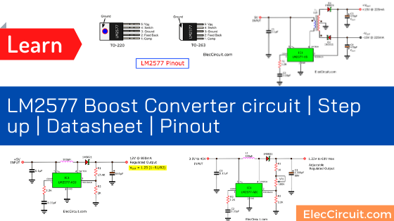
Lm2577 Boost Converter Circuit Step Up Datasheet Pinout
1918 (Venn's diagram is from 1904), named for English logician John Venn (1834-1923) of Cambridge, who explained them in the book "Symbolic Logic" (1881).

Simple Dc To Dc Converter Using 555 Time Ic 6v To 35 Volts Boost Converter
Apr 20, 2018 · This section starts with a non-synchronous boost schematic, gives equations for the duty cycle over the range of DC input voltage, and then contrasts that circuit with a synchronous boost. Something that has become more and more common as LED drivers, DC to AC inverters, and systems powered by solar panels, and other harvested energy sources ...
1
Boost converter I’m trying to understand how a simple DC to DC boost converter works yet I’m struggling pretty bad and have been losing my mind trying to figure it out. Take the following ( I apologise for my extremely crude drawing but I hope it illustrates my point) https://i.imgur.com/nc6Xmgd.jpg On the top I have the circuit in question and underneath I have a graph showing the current in the circuit as well as the voltage across the capacitor and the inductor. So my current wishy washy ...
Boost Converter Circuit Using Ic 555 Diy Electronics Projects
Circuit analysis — A boost converter (step-up converter) is a DC-to-DC power converter that steps up voltage (while stepping down current) from its input ( ...Overview · History · Applications · Circuit analysis

Dc Dc Hv Boost Converter 7 Steps Instructables
I’m trying to understand how a simple boost converter works yet I’m struggling pretty bad and have been losing my mind trying to figure it out. Take the following ( I apologise for my extremely crude drawing but I hope it illustrates my point) https://i.imgur.com/nc6Xmgd.jpg On the top I have the circuit in question and underneath I have a graph showing the current in the circuit as well as the voltage across the capacitor and the inductor. So my current wishy washy understanding is that init...

1 2 Or 1 5v Battery To 3 Volts Step Up Boost Converter Circuit
Provided they are designed and driven effectively, this technology can drastically reduce the size of DC-DC converters while maintaining ultra-high-efficiency operation. FTEX is leaning on the high-performance gallium nitride transistors offered by EPC driven to their full potential thanks to the high-performance MinDCet MDC901 drivers.
Adjustable Step Up Boost Converter Using Lm2577 Adj Circuit Diagram
I've been trying to solder and Marlette broken things. From. Age 1 (actually she 1 I cut my. Lamp. Witj scissors thinking I could use my scissors for better cutting McDonald's hspy. Meal boxes. Many years. And failed. Attempts later (last was 2016 trying to make and IR ball so for head tracking for flight simmimg. Don't think it worked stroked out then and burnt my carpet down leaving soldering iron 9m.the carpet passed 9ut. Bought a amazom special. Iron and the thermistor broke after leaving ...

The Dc Dc Boost Converter Part 3 Power Supply Design Tutorial Section 5 3 Power Electronics News
also micro-circuit, in electronics, "integrated circuit," 1959, from micro- + circuit (n.). Related: Microcircuitry.

5v Boost Converter
a aa aaa aaron ab abandoned abc aberdeen abilities ability able aboriginal abortion about above abraham abroad abs absence absent absolute absolutely absorption abstract abstracts abu abuse ac academic academics academy acc accent accept acceptable acceptance accepted accepting accepts access accessed accessibility accessible accessing accessories accessory accident accidents accommodate accommodation accommodations accompanied accompanying accomplish accomplished accordance according accordin...

Microcontroller Based Bidirectional Buck Boost Converter For Photo Voltaic Power Plant Sciencedirect
and 1 phase motor. Torque is measured in Inch Pounds. The input power from equation (1) is the electrical power of the battery. Sept. 1, 2008 Motor protection and motor circuit protection require different calculations. This calculator will show you how much your motor costs to operate and what you can save by improving efficiency. Welcome to survey form for calculator. Power: Btu/sec Btu/min ...
A Simple Dc Dc Boost Converter Circuit Using 555 Timer Ic
a aa aaa aaron ab abandoned abc aberdeen abilities ability able aboriginal abortion about above abraham abroad abs absence absent absolute absolutely absorption abstract abstracts abu abuse ac academic academics academy acc accent accept acceptable acceptance accepted accepting accepts access accessed accessibility accessible accessing accessories accessory accident accidents accommodate accommodation accommodations accompanied accompanying accomplish accomplished accordance according accordingl...
Buck Boost Voltage Converter Under Repository Circuits 23417 Next Gr
[\[](https://cdn.discordapp.com/attachments/727580829924196413/810525294909849600/Silver_Purple_ThickPNG.png)[Disclaimer\]](https://www.reddit.com/user/Zephylandantus/comments/ljpssb/disclaimer/) [\[First\]](https://www.reddit.com/r/HFY/comments/j66pee/tev_tricard/?utm_medium=android_app&utm_source=share) [\[Wiki\]](https://www.reddit.com/r/HFY/wiki/series/tev_tricard) [\[Previous\]](https://www.reddit.com/r/HFY/comments/p88yqy/tev_tricard_home/) ​ Hansen stood on the bridge a...

Buck Boost Circuit Design
Feb 24, 2012 · What is a Buck Boost Converter? The buck–boost converter is a type of DC-to-DC converter (also knownas a chopper) that has an output voltage magnitude that is either greater than or less than the input voltage magnitude. It is used to “step up” the DC voltage, similar to a transformer for AC circuits.. It is equivalent to a flyback converter using a single inductor instead of a transformer.
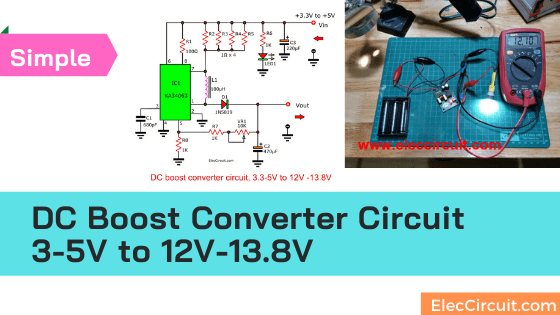
Dc Boost Converter Circuit 3 3 5v To 12v 13 8v Eleccircuit
a aa aaa aaron ab abandoned abc aberdeen abilities ability able aboriginal abortion about above abraham abroad abs absence absent absolute absolutely absorption abstract abstracts abu abuse ac academic academics academy acc accent accept acceptable acceptance accepted accepting accepts access accessed accessibility accessible accessing accessories accessory accident accidents accommodate accommodation accommodations accompanied accompanying accomplish accomplished accordance according accordingl...
What Is Boost Converter Basics Working Operation Design Of Dc Boost Converters
element14 has strengthened its portfolio of Power Integrations products to include the InnoSwitch3 IC family, featuring PowiGaN technology
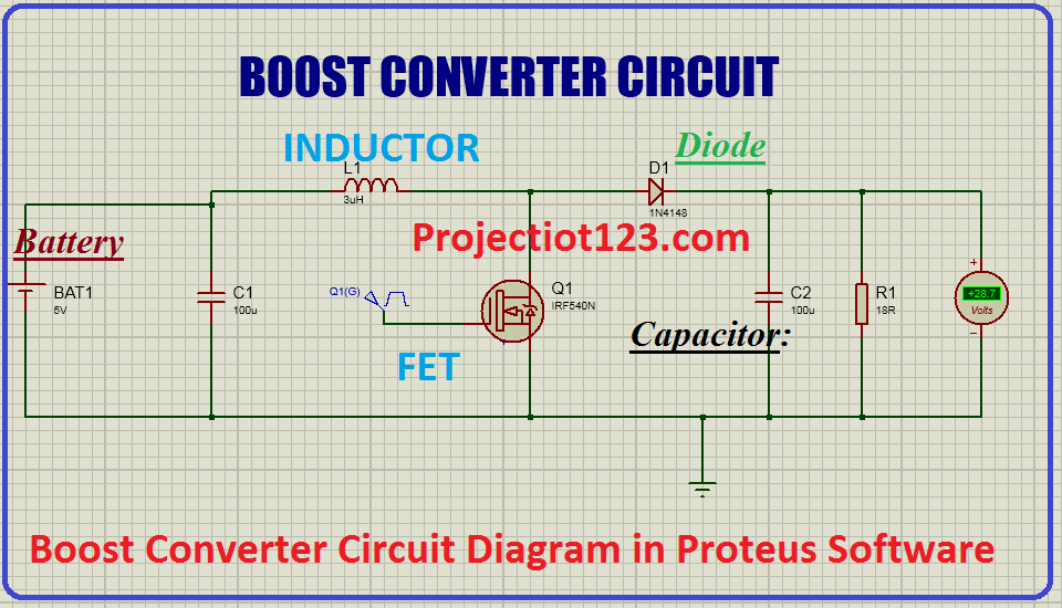
Boost Converter Circuit Diagram In Proteus Software Projectiot123 Technology Information Website Worldwide
A Boost Converter takes an input voltage and boosts it. In other words, its like a step up transformer i.e it step up the level of DC voltage (while ...

Buck Boost Converter What Is It Formula And Circuit Diagram Electrical4u
Buck boost converters. a buck boost converter is a type of switched mode power supply that combines the principles of the buck converter and the boost converter in a single circuit. like other smps designs, it provides a regulated dc output voltage from either an ac or a dc input. Buck boost converters are ideal for use in portable devices, where the power source is frequently a single battery ...
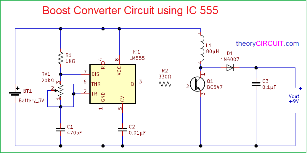
Boost Converter Circuit 555
a aa aaa aaron ab abandoned abc aberdeen abilities ability able aboriginal abortion about above abraham abroad abs absence absent absolute absolutely absorption abstract abstracts abu abuse ac academic academics academy acc accent accept acceptable acceptance accepted accepting accepts access accessed accessibility accessible accessing accessories accessory accident accidents accommodate accommodation accommodations accompanied accompanying accomplish accomplished accordance according accordingl...
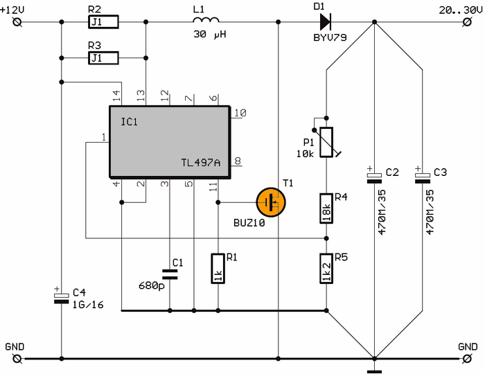
12v To 30v Tl497 Dc Dc Converter Circuit 20v 30v Adjustable Electronics Projects Circuits
a aa aaa aaron ab abandoned abc aberdeen abilities ability able aboriginal abortion about above abraham abroad abs absence absent absolute absolutely absorption abstract abstracts abu abuse ac academic academics academy acc accent accept acceptable acceptance accepted accepting accepts access accessed accessibility accessible accessing accessories accessory accident accidents accommodate accommodation accommodations accompanied accompanying accomplish accomplished accordance according accordi...
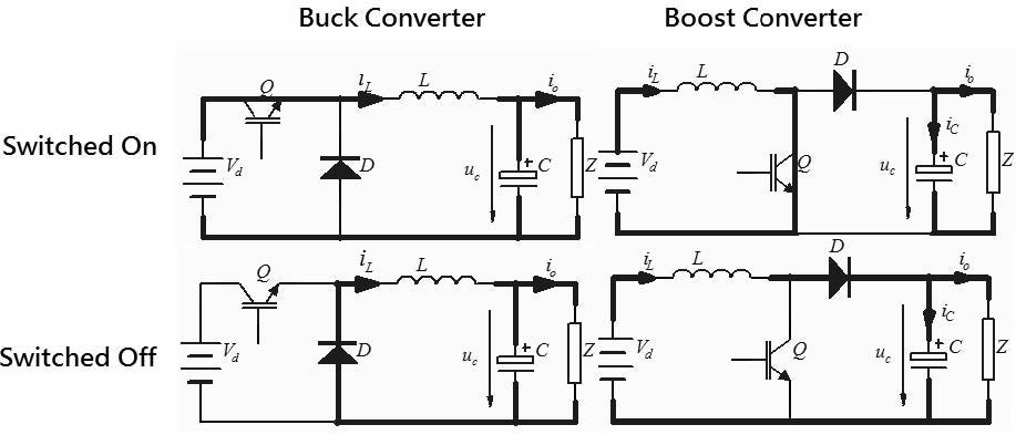
Switching Circuits Buck And Boost Converters By Savini Hemachandra Medium
The 2022 Moto G Power once again features a 5,000mAh battery Motorola claims can provide up to three days of continuous use. This time around, the company has gone with a 6.5-inch display that features a panel with 720p resolution and a 90Hz refresh rate. New to this latest model is a tweaked triple camera array highlighted by a 50-megapixel ...

3 7v To 5v Boost Converter Circuit Diagram Archives Theorycircuit Do It Yourself Electronics Projects
Sep 16, 2021 — The inductor tries to resist change in the current to provide a constant input current and hence the Boost converter acts as a constant current ...
How To Build A Dc To Dc Boost Converter Circuit
To differ the enter voltage, some make use of DC-DC converters, whereas extra advanced built-in circuits ramp the present by adjusting the resistance between the charger enter and the battery terminals. Save an extra 10% OFF on top of the 50% discount with this Coupon! Features of BoltzPro
What Is Boost Converter Basics Working Operation Design Of Dc Boost Converters
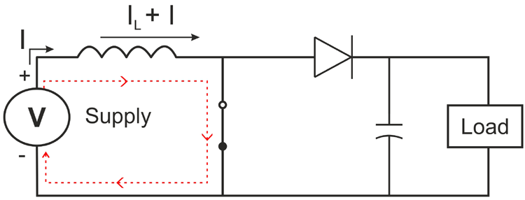
3.1 GENERAL BOOST CONVERTER CONFIGURATION In a boost converter, the output voltage is greater than the input voltage – hence the name “boost”. A boost converter using a power MOSFET is shown below. Fig. 3.1.1 Circuit diagram of Boost Converter. [1] The function of boost converter can be divided into two modes, Mode 1 and Mode 2. Mode 1

Diy Electronics Electronic Schematics Electronics Circuit Circuit Diagram
May 23, 2021 — A circuit of a Boost converter and its waveforms are shown below. The inductance, L, is 20mH and the C is 100µF and the resistive load is 20Ω.
Boost Circuit Design 35 Images Boost Converter Circuit Design Pdf Boost Converter Design Circuit Scientific Diagram Boost Converter Circuit
late 14c., "a circumference; a periphery, a line going around (an area), whether circular or not; a circular or circuitous course," from Old French circuit (14c.) "a circuit; a journey (around something)," from Latin circuitus "a going around," from stem of circuire, circumire "go around," from circum "round" (see circum-) + ire "to go" (from PIE root *ei- "to go"). From c. 1400 as "space enclosed within certain limits." Hence, "district in which any business involving periodic journeys is done (1570s), especially of judicial assignments involving the journey of a judge from one place to another; in reference to routes followed by itinerant entertainers from 1834. Hence also circuit-rider "Methodist minister who rides a circuit, preaching successively in different stations" (by 1834); to ride circuit "take a roundabout course" is from 1650s. Electrical sense "arrangement by which a current is kept up between two poles" is from 1746. Circuit-breaker "device for automatically opening an electrical circuit" is r

Circuit Diagram Of Boost Converter From Fig 3 During The Switch Is Download Scientific Diagram
"pertaining to schemes," 1701, from Latin stem of scheme (n.) + -ic. Noun meaning "diagram" is first attested 1929. Related: Schematical (1670s).
0 Response to "38 boost converter circuit diagram"
Post a Comment