38 mac valve wiring diagram
wiring diagram index, 12v NAME DESCRIPTION Page NAME DESCRIPTION Page AA-O POWER DISTRIBUTION 1/2 2 GD LIGHTING-FORWARD/SIGNAL (CXU,GU7,GU8) 30 Mac Trailer Wiring Diagram - People today understand that trailer is a vehicle comprised of quite complicated mechanics. This automobile is designed not just to travel 1 location to another but also to take heavy loads. This article will be discussing mac trailer wiring diagram.What are the advantages of understanding such understanding?
The Mac Pilot Valve is connected to the Top of the Mac Valve (3100317). This valve is an electric over air solenoid valve used to dump. the air ride suspension. This Valve has been replaced by the Ride Air valve on 2007/2008 trailers. To see complete assembly refer to page 49. Part No: 3100106. Description:

Mac valve wiring diagram
Jul 13, 2018 · Solenoid Valve Wiring Diagram Png 800x614px Solenoid Valve. Wiring Diagram For Solenoid Valve Example Wiring Diagram. Solenoid Valves Interfaces Between The Electric Control Level And. Woods Spr84 Power Rake Spr72 Spr84 Spr96 Power Rake Hydraulic. 8f614 Mac Solenoid Valve Wiring Diagram Digital Resources. Mac Valves. For over 70 years MAC Valves, Inc. has been a global manufacturing leader of pneumatic and more recently fluid valves for industry. MAC’s innovative technology featuring our patented poppet, spool and recently developed Bullet Valve®️ raised the performance bar in valve technology. We design and manufacture valve solutions ... Directional air control valves are the building blocks of pneumatic control. Pneumatic circuit symbols representing these valves provide detailed information about the valve they represent. Symbols show the methods of actuation, the number of positions, the flow paths and the number of ports. Here is a brief breakdown of how to read a symbol.
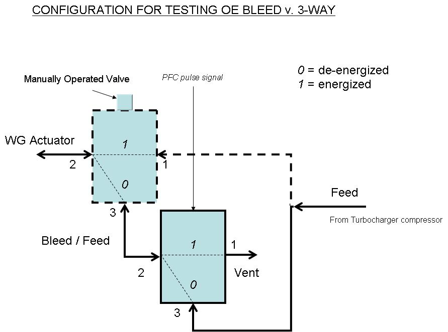
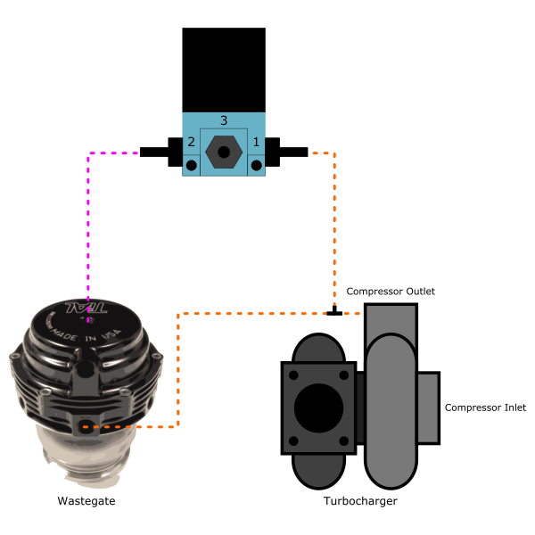
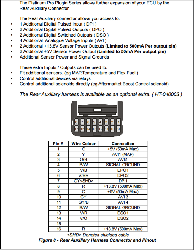
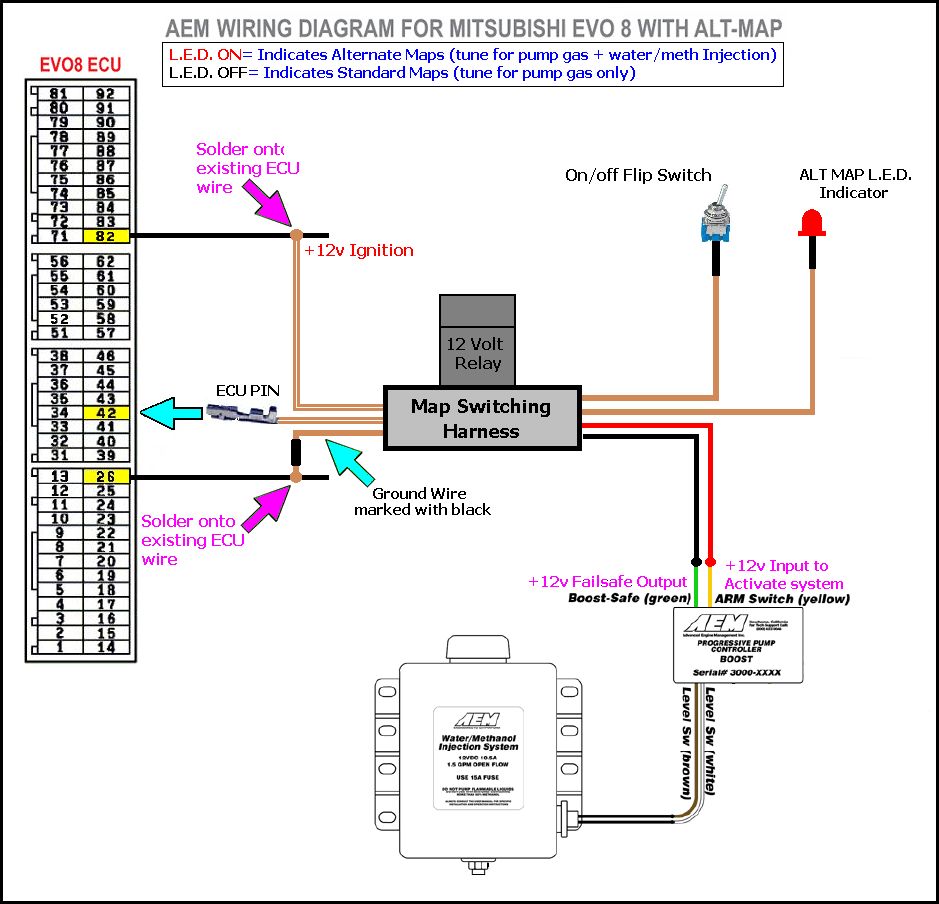
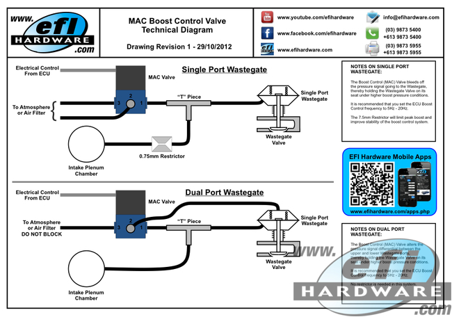
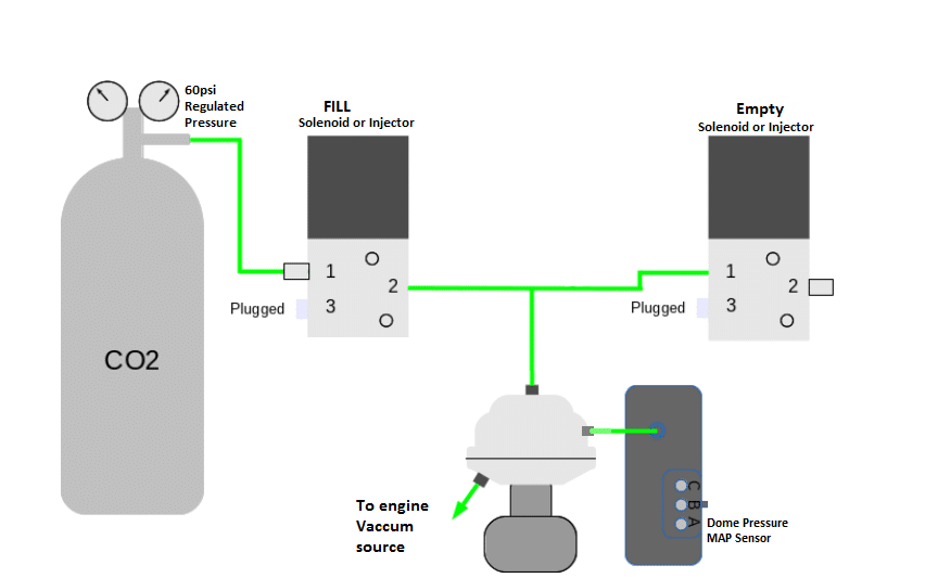
Mac valve wiring diagram. I've been having issues with the low dollar 4 bar MAP sensor not scaling correctly, so Ive given up and went to boost control. I'm currently setting up dome and dual MAC valves on my setup with CO2. How are you guys wiring up these? I've sat there forever wondering. I know two go to 12V keyed, one + & one - etc., but the output list I got with the Terminator kit are all positive and no idea on ... - For dual pressure valves with lights on valve body (see page 293 for use with sandwich regulators), replace by 6. Note : 1. The valve less base is always the same for internal or external pilot. These options are effected in the base. 2. To order bases without the valve, choose the base from the above table, then add 6300D as a prefix. The MAC 82 Series is a versatile 4-way solenoid piloted spool valve. This series features our balanced poppet in the pilot and an air/spring return for consistent shifting regardless of inlet pressure fluctuations.. Our balanced spool means the valve can be piped as a 4-way, 3-way, 2-way, normally closed or normally open or can be used for vacuum, diverter or selector applications. MAC 1175 Summer Air Circulator Receptacle Unit Switch-+ 7. Run the wires attached to the timer through the bushing at the bottom of the control box and install the bushing. 8. Connect the wires per the wiring diagram. (See Figure 1) 9. Attach the control box cover. 10. DELAY ON MAKE dial should be set for 60 seconds. 11. DELAY ON BREAK dial ...
power distribution frc 1/2 wiring diagram: aa spf44a spx03ea3 fb2a1-0.8 ag:0 b a17.b:2 ai:4 c frc_j3:c5 aq:1 b mcsc:a9 f61a1-0.8 hb:2 d a131b.a:4 f15a1-5.0 bi:3 c x210a.a:d f87 15a cust. a b f71 15a center pin hot a b f60 30a hvac fan a b f61 5a lvd sens/ vendor ttu a b f76 30a 3968162 a f05 30a lecm4 b f06 20a rh sleeper pwr ports/ console b ... Wiring Information MAConnect Information™ Precautions Page 31 32 34 MAC Valves Commonly Ordered Products Catalog Table of Contents. Valve Function 2-Way Valve Function Normally Closed (N/C)=Non-Passing. Normally Open (N/O)=Passing. Plug a port on a 3-way to make it function like a 2-Way. Typical Application: an Airjet Blow Off application. Jun 21, 2021 · Mac Valve Wiring Diagram – One of the most difficult automotive repair tasks that a mechanic or repair shop can say yes is the wiring, or rewiring of a car’s electrical system. The misfortune in reality is that every car is different. considering bothersome to remove, replace or repair the wiring in an automobile, having an accurate and detailed mac valve wiring diagram is critical to the execution of the fix job. MAC Advantage Brochure. 16 Pages. CIRCUIT BAR CATALOG. 288 Pages. Proportional pressure controller. 89 Pages. CURRENT TECHNOLOGY CATALOG. 359 Pages. NEW TECHNOLOGY CATALOG.
3. Wire the fill (+) solenoid to the to the ECU's output pin that you chose. In this example it was J1B10 (or pin G on the IO connector). 4. Connect the other side of the solenoid to a switched 12V power source. 5. Wire the vent (-) solenoid to the to the ECU's output pin that you chose. In this example it was J1B3 (or pin H on the IO ... 24712201 Electric / Air Control Valve 1945 Normally Closed 24712202 Electric / Air Control Valve 2345 Normally Open 24712212 12V Parker Inline Pilot Valve 24000604 Breather www.mactrailer.com MAC Trailer Mfg. 1-800-795-8454 parts@mactrailer.com Part Sales 1-800-647-9424 TS MATIC 3 The Hydra-Mac Skid Steer Loader Operators Manual fits the Hydra-Mac. Always in stock so you can get it fast. Also available as a pdf download. Jensales offers the finest in Manuals, Parts, and Decals. Keywords: HM-O-9CL+{72891}, HM-O-9CL+, Hydra-Mac, Hydra-Mac Skid Steer Loader Operators Manual Created Date: 2/9/2007 4:13:45 PM Always check the latest information at the "Wiring Diagrams" location. Utilization of Body Builder connectors ordered and provided by Mack is strongly recommended as your power, lighting, and ground source for body installation, PTO installation, and operation. Cutting into wiring harnesses is not recommended as it may affect CAN Bus messaging.
Diagram mac control valve wiring full version hd quality old honeywell v8043 need help zone valves doityourself com community forums adding to weil mcclain he boiler heating the wall locating c for ecobee install with v8043e1012 connect line voltage hot water piping 1 faqs how or wire a taco 24v sandy ed u can you terry love plumbing… Read More »
HEATING ONLY - WIRING DIAGRAMS instructions and wiring diagrams. See Figures 4,5,6,7 and 16 C. Use of Indirect Storage Tank (DHW): • Indirect storage tank, use only tank sensor to interface with boiler. Wire sensor to M2 terminals #9 and #10. • Use of booster pump to increase flow rate to indirect tank is not recommended by manufacturer.
Committed to the design and manufacture of high-tech valve solutions for our customers around the globe. Since 1948, MAC Valves, Inc. has worked to establish and maintain global technological leadership in the design and manufacture of pneumatic and fluid valves, proportional valves, flow control, and regular technology.
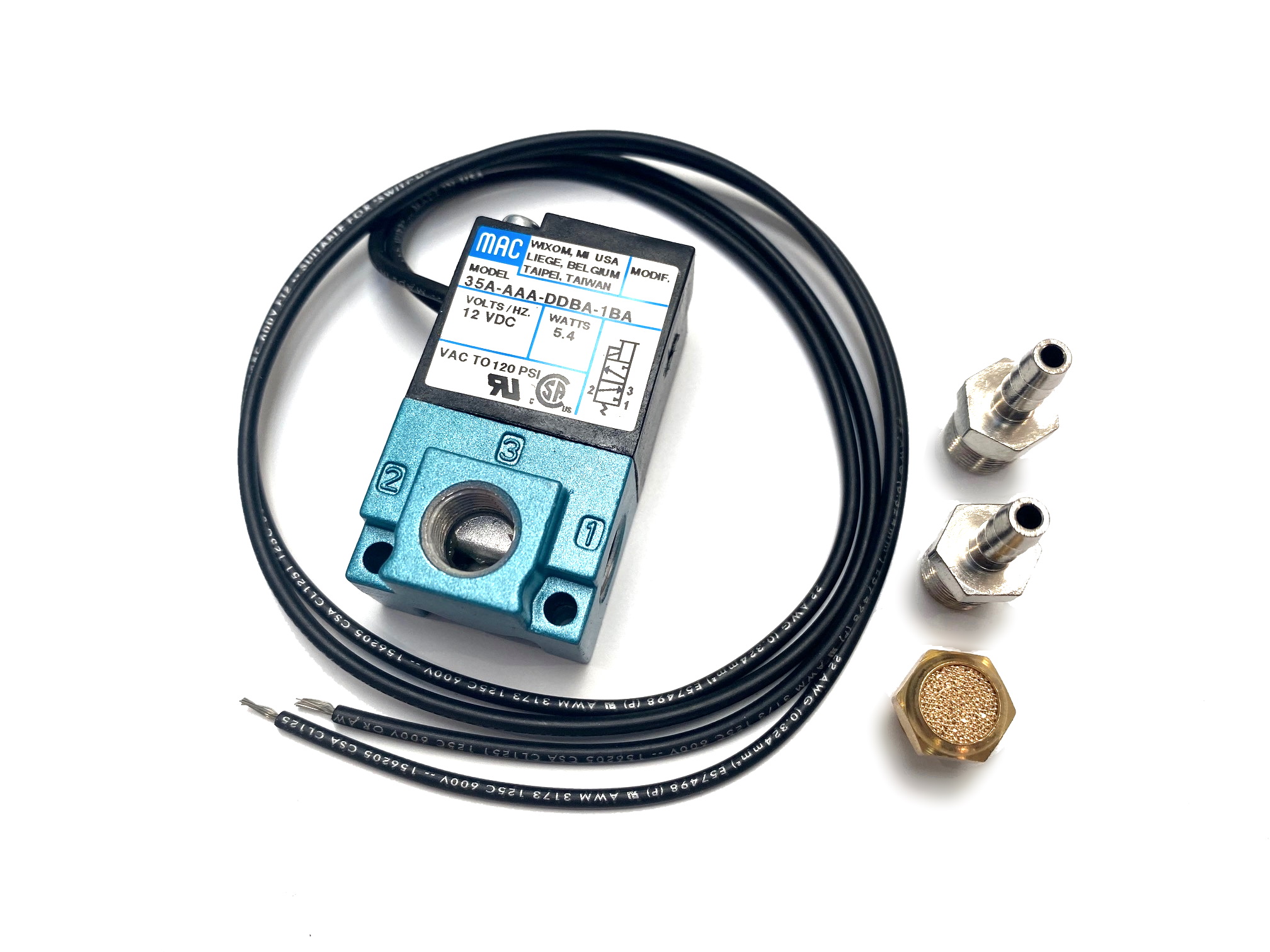
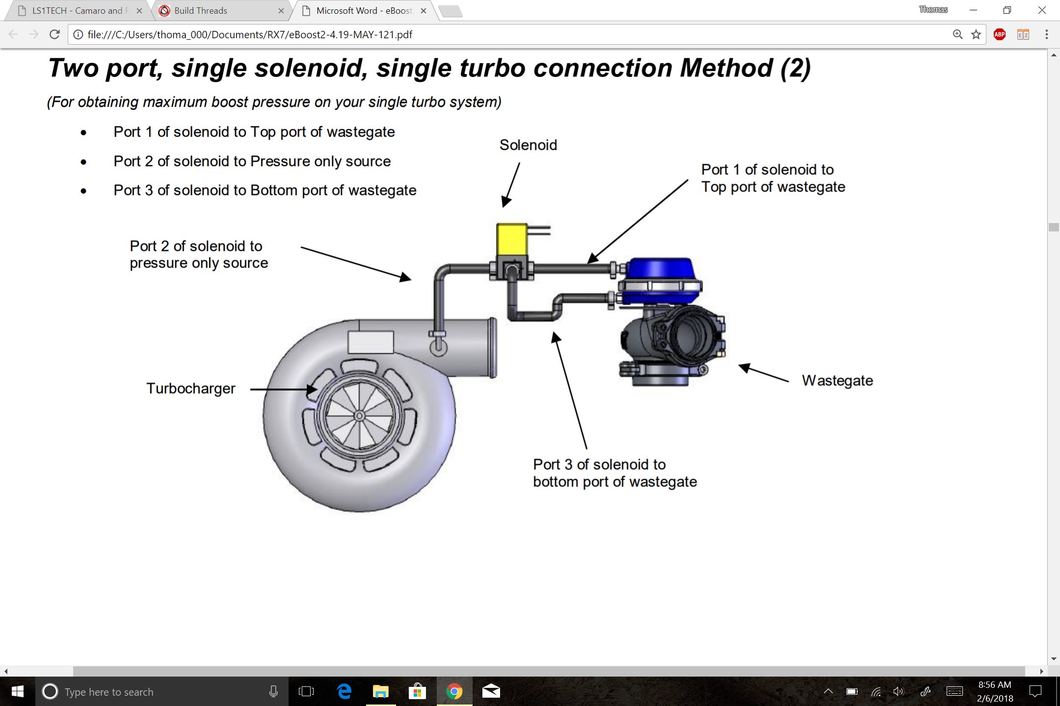
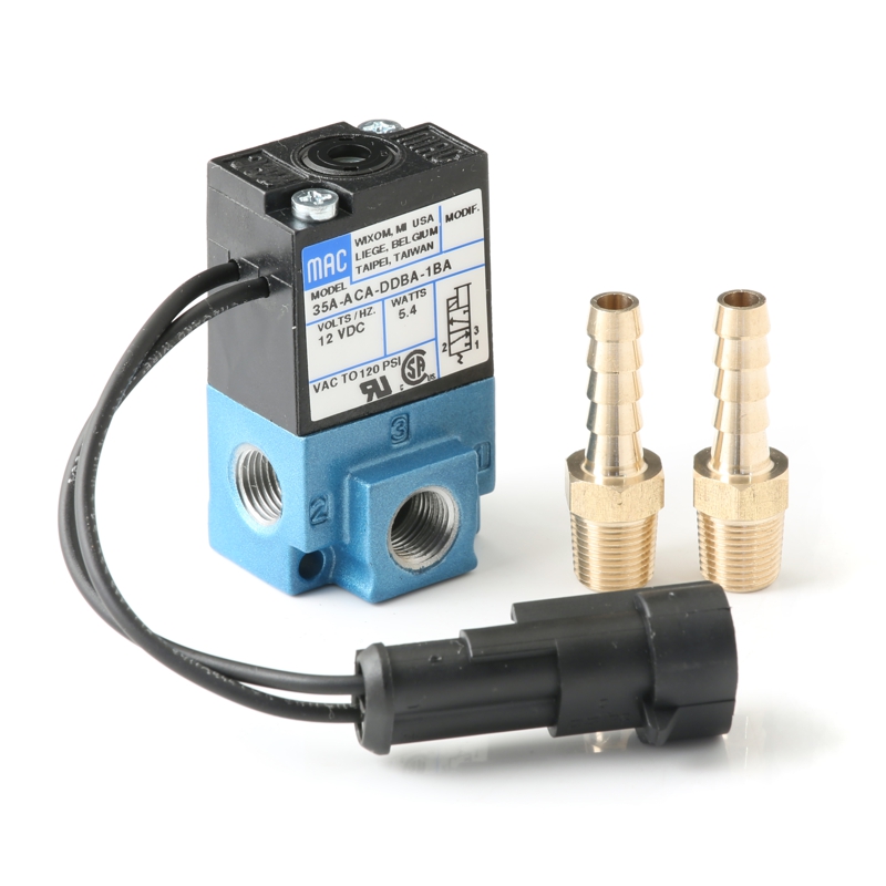
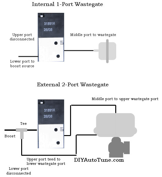
This kit includes 1/8″ barb fittings and mounting hardware. Maximum pressure is 125 psi, so this can be used even on wild high pressure compound turbo setups. Note: This valve is a perfect match for use with our MS3-Pro ECU as well as the MegaSquirtPNP and DIYPNP line of PNP EMS systems. Vacuum diagrams for current model boost control solenoid.
wiring diagram − type om w/obd 2013 eng product schematics 22437775 04 1 (2) 1 (52) wiring diagram index name description page ... valve 25a b frc1:f2 f29b2−0.8 cb52 spare/ brk. wear 15a b cb55 cir. heated mirrors 20a b f56 fuse telma 10a b cb57 hvac roof cond. fan 15a b spx2d frc1:f1 cb30 cir. brkr., muncie live pack 10a a b
This manual contains information and diagrams related to wiring most Holley EFI products including ECU's, ignition systems, nitrous systems, water/methanol injection systems, sensors, and more. 3 1.1 Important Wiring "Do's and Don'ts ...
WIRING DIAGRAM The SV71 and SV73 solenoid valves are a compact, light-weight solenoid that can be used in intrinsically safe applications. It is important to note that a proper safety barrier needs to be used in conjunction with the solenoid valve. Solenoids come standard with both 3-Way and 4-Way field conversion kits.
Dec 20, 2020 · Mac Valve Wiring Diagram. Mac Valve Wiring Diagram from www.therangerstation.com. Effectively read a wiring diagram, one has to know how the particular components in the method operate. For example , in case a module will be powered up and it sends out a new signal of fifty percent the voltage and the technician would not know this, he would think he has a challenge, as he or she would expect the 12V signal.
MAC Valves, INC. 30569 Beck Rd; Wixom, MI 48393; 248 624 7700; 1 800 MAC VLVS; mac@macvalves.com "Valves That Don't Stick" ©2021 macvalves inc. ...
Vee Port PRO for Subaru WRX (01-07), STI (01-08), Forester XT (06) Dual Port SmartPort - 2015-on Subaru WRX. Dual Port SmartPort - Mk 6 Golf R, Mk 6 Scirocco R, and the Audi S3 (2006-2013) Supersonic SmartPort - 2013+ Ford F150 3.5L EcoBoost. Borg Warner/KKK Compressor Cover Specific BPV.
• Pilot valve : PME-XXyZZ, including seal 16337. • Pressure seal between valve and base : 16246. • Mounting screw valve to base (x4) : 32201. • BSPP threads. Spare parts : Options : dimensions technical data Dimensions shown are metric (mm) Consult "Precautions" page 364 before use, installation or service of MAC Valves 100% 18 100% ...
Help With Wiring A Honeywell Thm5320r To V8043e1012 Zone Valve Doityourself Com Community Forums. Mac control valve wiring diagram full need help honeywell zone valves ecobee install with heating faqs how to manuals installation adding weil mcclain he hot water boiler piping v8043e1012 v8043 for at72d 2 s plan central system combination zones home v4043 motorized wire taco hvac talk air ...
Directional air control valves are the building blocks of pneumatic control. Pneumatic circuit symbols representing these valves provide detailed information about the valve they represent. Symbols show the methods of actuation, the number of positions, the flow paths and the number of ports. Here is a brief breakdown of how to read a symbol.
Mac Valves. For over 70 years MAC Valves, Inc. has been a global manufacturing leader of pneumatic and more recently fluid valves for industry. MAC’s innovative technology featuring our patented poppet, spool and recently developed Bullet Valve®️ raised the performance bar in valve technology. We design and manufacture valve solutions ...
Jul 13, 2018 · Solenoid Valve Wiring Diagram Png 800x614px Solenoid Valve. Wiring Diagram For Solenoid Valve Example Wiring Diagram. Solenoid Valves Interfaces Between The Electric Control Level And. Woods Spr84 Power Rake Spr72 Spr84 Spr96 Power Rake Hydraulic. 8f614 Mac Solenoid Valve Wiring Diagram Digital Resources.












0 Response to "38 mac valve wiring diagram"
Post a Comment