38 shear and moment diagram
Shear and bending moment diagrams are analytical tools used in conjunction with structural analysis to help perform structural design by determining the value of shear force and bending moment at a given point of a structural element such as a beam. ‰The bending moment and shear force diagrams of the beam are composites of the V and M diagrams of the segments. These diagrams are usually discontinuous, or have discontinuous slopes. At the end-points of the segments due to discontinuities in loading.
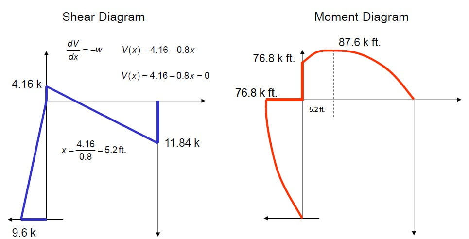
Figure 9: Shear and moment distributions in a cantilevered beam. positions along the beam, it is necessary to integrate over each section between loads separately. The moment diagram is now parabolic, always being one order higher than the shear diagram.
Shear and moment diagram
2,000 N 1,000 N / m 6 m 4 m 2 m Use a ruler to prepare the shear force and bending moment diagrams for the beam. Determine the magnitude of the maximum bending … CIVL 3121 Shear Force and Bending Moment Diagrams Shear and Moment Diagrams The slope of the moment diagram over the interval L < x < 2L is the equal to value of the shear; in this case V = 0... This video is sponsored by McGraw-Hill's AccessEngineering.AccessEngineering helps students solve problems using real-world examples to show how fundamental...
Shear and moment diagram. Bending moment diagram (BMD) Shear force diagram (SFD) Axial force diagram. Invert Diagram of Moment (BMD) - Moment is positive, when tension at the bottom of the beam. Calculate. Load and Shear Force Relationships Change in Shear rea under Loading Curve between d w( ) d and (34) LECTURE 3. BES: SHER ND OENT DIGRS (GRPHICL) (5.3) Slide No. 3 Similarly, applying moment equilibrium to the free-body diagram of Fig. 0b we obtain ( ... + a( w ) + c 0; - L L L L... Shear and moment functions can be plotted in graphs called shear and moment diagrams. In order to properly design a beam, it is important to know the variation of the Draw the shear and moment diagrams for the beam shown. Solution: From the free-body diagram of the left segment, we apply... Shear and bending moment diagrams depict the variation of these quantities along the length of the member. Proceeding from one end of the member to the other, sections Shear and Bending Moment Diagrams 7. 8. 2. Principle of Superposition. Example Problem Shear and Moment Diagrams.
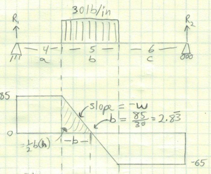
I recently had this problem on an exam and after looking at Beamguru my Moment Diagram is completely different than theirs (the shear was the same) so I wanted to ask you guys if this is accurate. What doesn't make sense to me is how there are moments at the pin and roller supports. It should be zero there since those parts don't transmit a moment, right? And looking at the 6 feet from the far left to the first support, the area under the shear diagram is negatively increasing but the moment... Shear and Moment Diagrams Consider a simple beam shown of length L that carries a uniform load of w (N/m) throughout its length and is held in equilibrium by reactions R1 and R2. Assume that the beam is cut at point C a distance of x from he left support and the portion of the beam to the right of C be removed. The portion removed must then be replaced by vertical shearing Structural Axial Shear and Bending Moments. Shear and Moment Diagrams : Now that the shear and moment is known for each section of the beam, the results can be plotted. The resulting graphics are called the shear diagram and moment diagram. This free online structural frame calculator will generate and find the bending moment and shear force diagrams of a 2D frame structure. The free version allows you to input frames with a maximum of 3 members with applied point loads and moments for 2D frame analysis.
Bending moments are considered positive when the moment on the left portion is clockwise and on the right anticlockwise. This is referred to as a sagging The shearing force suffers sudden changes when passing through a load point. The change is equal to the load. The bending Moment diagram is a... May 27, 2015 · date: 19-april-2017 . this is a great work !, indeed, any ordinary folks, engineers or non-engineers can make use of this software program calculator (beta) to check, verify and simulate his/her conceptual design works for any steel reinforced concrete house or apartment’s sectional member such as rectangular, i-beam, etc. Crosspost from r/hwforcash Hello! I am a US Engineering student taking Engineering Statics. My exam is on Tuesday, Jan 12th from 6-7:15 pm. It is online, live, and webcam proctored. I need someone who is really good at Statics, specifically Shear and Bending Moment, who can help me on my exam. Please only respond if you know Statics really well and can answer quickly, as the exam does not give a lot of time to answer. There are 4 questions, and I can provide you a review that will be similar... Mar 04, 2019 · With reference to Figure A.4 diagram and taking moment at the point, P conservatively neglecting the effect of passive pressure hence: RM= W 2 (0.75) + W 3 (0.75) ... Check the Wall Thickness for Shear. The nominal shear is equal to the lateral forces on the retaining wall, neglecting the effect of passive pressure which will give us:
Shear And Moment Diagram For Frame Question Physics Forums
Shear and moment diagram — Shear and bending moment diagrams are analytical tools used in conjunction with structural analysis to help perform structural design by determining the value of shear force and bending moment at a given point of an element. Using these diagrams… …
Solution To Problem 419 Shear And Moment Diagrams Strength Of Materials Review At Mathalino
In dynamics a kinetic diagram is a pictorial device used in analyzing mechanics problems when there is determined to be a net force and/or moment acting on a body. They are related to and often used with free body diagrams, but depict only the net force and moment rather than …
Moment Diagrams Examples
Shear And Moment Diagrams Of Beams Shear Force Bending Moment Diagram Learn Engineering. Shear And Moment Diagrams Solved Section B 1 Draw The Shear And Moment Diagram For.

Shear And Moment Diagram Images Shear And Moment Diagram Transparent Png Free Download
Shear and moment diagrams and formulas are excerpted from the Western Woods Use Book, 4th edition, and are provided herein as a courtesy of Western Wood Products Association.

Shear And Moment Diagram Wikipedia
Bendingmomentdiagram.com is a free online calculator that generates Bending Moment Diagrams (BMD) and Shear Force Diagrams (SFD) for most simple beams. The calculator is fully customisable to suit most beams; which is a feature unavailable on most other calculators.

How To Plot Bending Moment Diagram From Shear Force Diagram Engineering Stack Exchange
You probably can tell from the examples previously that the shear force SF and bending moment BM varies along the beam, due to the varying loads. So how do we conveniently see the SF and BM along the beam? Well that's what the SF and BM diagrams are for!
What Pc Software Allows Us To Draw Bending Moment Shear Force And Normal Force Diagrams Quora
Could anyone help me find the shear and moment diagram for this problem: https://m.imgur.com/a/8LOlS. I would appreciate if you could explain a little bit how you solved it too. Thanks a lot!
Bending Moment Diagram From Shear Force Diagram Engineering Stack Exchange
The Timoshenko–Ehrenfest beam theory was developed by Stephen Timoshenko and Paul Ehrenfest early in the 20th century. The model takes into account shear deformation and rotational bending effects, making it suitable for describing the behaviour of thick beams, sandwich composite beams, or beams subject to high-frequency excitation when the wavelength approaches the thickness of the beam.
The Ultimate Guide To Shear And Moment Diagrams Degreetutors Com
Hello everyone. I'm working on a research paper that requires ABAQUS. I'm new to the program but I'm getting the hang of it, thankfully. However, I've been trying to plot the shear and moment diagrams on my frames but I'm left with this giant spectrum that's almost hiding the diagrams. Here's a screenshot: https://imgur.com/Zqr7h6w . &#x200B; Does anyone know how I can hide the spectrum so I can show the contours alone? Thanks in advance.
10 Shear Force Diagram Bending Moment Diagram
Shear-moment diagrams for some common end conditions and loading configurations are shown within the beam deflection tables at the end of this page. The shear at any point along the beam is equal to the slope of the moment at that same point: The moment diagram is a straight, sloped line...

Shear Force And Bending Moment Diagrams Download Scientific Diagram
Draw the shear and bending-moment diagrams for the beam and loading shown, and determine the maximum absolute value (a) of the shear, B (b) of the bending moment. 300 mm.

Brief Information About Shear Force And Bending Moment Diagrams Engineering Discoveries Bending Moment Shear Force Civil Engineering Design
Hello, I am a US Engineering student taking Engineering Statics. My exam is on Tuesday, Jan 12th from 6-7:15 pm. It is online, live, and webcam proctored. I need someone who is really good at Statics, specifically Shear and Bending Moment, who can help me on my exam. Please only respond if you know Statics really well and can answer quickly, as the exam does not give a lot of time to answer. There are 4 questions, and I can provide you a review that will be similar to the exam. If you can sol...

How To Calculate And Draw Shear And Bending Moment Diagrams 13 Steps Instructables
A free, online multi-span beam calculator to generate shear force diagrams, bending moment diagrams, deflection curves and slope curves for beams with complex boundary conditions, multiple spans and multiple loads. Select a beam and enter dimensions to get started.

Bending Shear And Moment Diagram Graphical Method To
Shear force and bending moment diagrams tell us about the underlying state of stress in the structure. Building on our discussion of bending moments, the shear force represented in the shear force diagram is also the resultant of shear stresses acting at a given point in the structure.
Solved Draw The Shear And Moment Diagrams And Determine The Maximum Values Of Shear And Moment Assume The Supports At A And C Are Rollers And At B Course Hero
So, I'm studying for a test, and I can't find anywhere how to draw and calculate shear and moment diagrams for a Gerber beam, all the tutorials only show the single rigid beam example. So if anyone has any examples or explanations, I'd be very thankful. Cheers!
Mechanics Map Shear And Moment Diagrams
Footing Design of Shear Wall per ACI 318-14 Meyerhof bearing capacity calculator meyerhof method, shallow foundation bearing capacity, mayerhof method, download civil engineering sheets

Book Solution 6 2 Mechanics Of Materials By R C Hibbeler Draw The Shear And Moment Diagrams For The Simply Supported Beam Civil Engineering Soft Studies
Basic shear diagram[edit | edit source]. What if there is more than one force, as shown in the diagram below, what would the shear force diagram look As you would have noticed when working out the bending moment and shear force at any given point, sometimes you just work it out at the point, and...
Shear Force And Bending Moment Diagrams Graphical Method Slide Share
You have finished calculating and drawing shear and bending moment diagrams as well as an approximate deflection diagram. This will help you become better at calculating all typed of these problems, and you will certainly be ahead of the curve the next time you need to know how to do this.

Civil Engineering Mechanics Cantilever Beam Shear Force And Bending Moment Diagram Practice Problem Facebook
Learning how to drawing shear force diagrams (SFDs) and bending moment diagrams (BMDs) is a necessary skill to learn for engineering students learning statics, mechanics of materials, and structural analysis. There is a long way and a quick way to generate them.
Lo Unisa Edu Au
As part of my graduate program I wrote some software that basically analyzes any beam that the user enters and determines support reactions/deflections. I accomplished this using stiffness matrices. However I now want to be able to graph the shear, moment and deflection diagrams for the same beam. I could probably brute force this by developing equations from my support reactions/applied loading and integrating as necessary but this seems cumbersome. Is there a way to make use of some of the w...
10 Shear Force Diagram Bending Moment Diagram
Draw the shear force and the bending moment diagram, find the magnitude and the location of the maximum shear force and the maximum bending moment ? cut W0.980N us: : 2.9+N I 0 At The 1.270 aro.am boo.offio Rgo 2.690N 0.44m
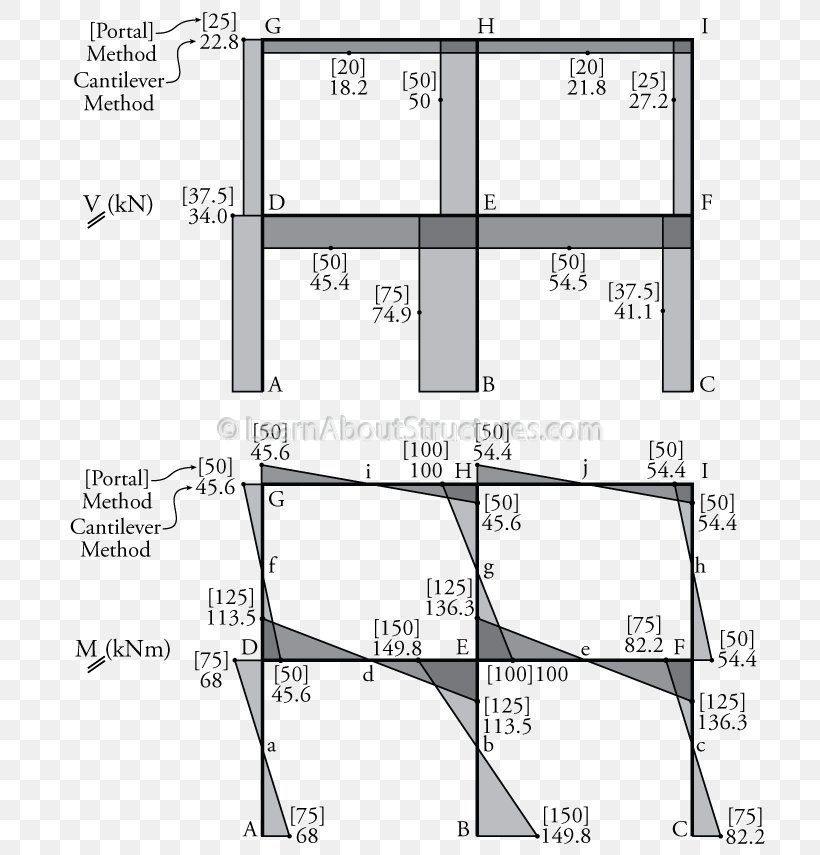
Shear And Bending Moment Diagrams For Frames Construction How
Moment-Shear Diagram Calculator Tool. For complex beams with more than a couple loads, determining moment and shear diagrams is very difficult. Thus, most structural engineers will use a beam analysis tool to calculate moments and shear. A simple one availble for mobile devices.
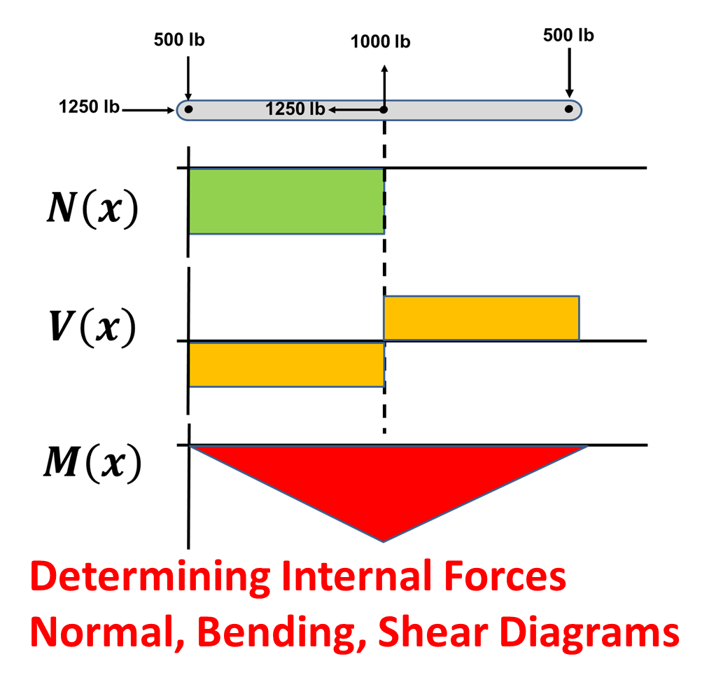
Determining Internal Forces Normal Shear And Bending Moment Diagrams Top Dog Engineer
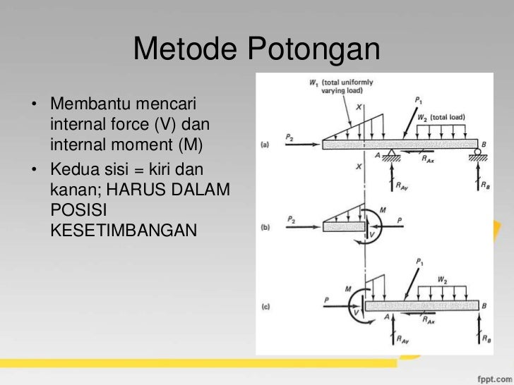
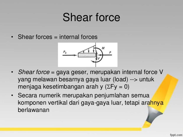
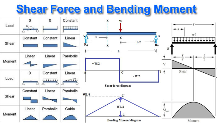
Example Problem Shear and Moment Diagrams. Beam Sign Convention for Shear and Moment. 3. Internal Shear Force (V) ≡ equal in magnitude but opposite in direction to the algebraic sum (resultant) of the components in the direction perpendicular to the axis of the beam of all external loads and...

The Shear And Moment Diagrams Of The Gfrp Girder Download Scientific Diagram
I have been looking for suitable reference materials but with no success. Here is one of the questions that I am stuck at: Find the shear and bending moment diagram of the following rigid To get the vertical reactions we need to calculate the moment around a given point, which must be equal to zero.

Drawing Bending Moment Diagrams Effectively Mechanicalbase
Hey guys, I'm a late-twenties ME who's reteaching myself my undergrad curriculum for the sake of technical interviews (ugh). Thanks bay area. Anyway, I'm rolling through my statics and I'm having a little problem with shear and moment diagrams. The concept is straight forward. I've no problem calculating the reaction forces. But when I'm drawing my shear diagram, cutting my beam from left to right, I struggle to figure out which direction to draw my shear. My 1960's statics textbook is good bu...

Shear And Moment Diagram Wikiwand
Shear Failure Here is a range of average shear stressesthat can be used to estimate shear failure : The average shear stress that concrete can withstand can be approximated by this range For most cases and especially regions of high shear and moment, flexural cracks will form first, reducing shear stress at diagonal cracking to min In

Drawing Shear And Moment Diagrams For Beam Youtube
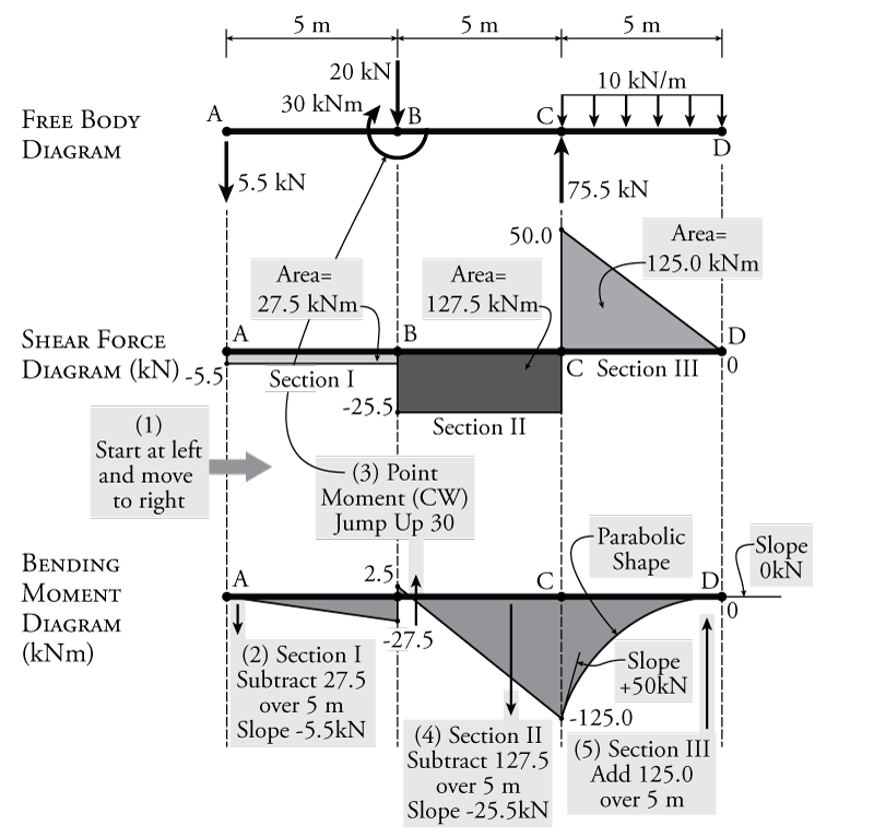
3 Shear and moment diagram Axial load diagram Torque diagram Both of these diagrams show the internal forces acting on the members. 13 Boundary cond for V and M M=5x M=10-5x. 14 Solve it Draw the shear and moment diagrams for simply supported beam.
Web Ncyu Edu Tw
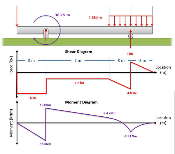
Shear force Diagram The shear force remains zero till the 10kN load is reached. It is then constant and equal to -10 kN till it reaches the point C where Bending moment diagram: Let us draw the bending moment diagram from the shear force diagram, keeping in mind the fact that the slope of bending...
1 4 Internal Forces In Beams And Frames Engineering Libretexts
Bending Moment Diagrams. Shear Force Diagrams. Calculate the Deflection of Steel, Wood and Other Materials. Welcome to our free online bending moment and shear force diagram calculator which can generate the Reactions, Shear Force Diagrams (SFD) and Bending Moment Diagrams...
Shear And Moment Diagram Shear Force Portal Frame Bending Moment Png 800x855px Diagram Architectural Engineering Area
This video is sponsored by McGraw-Hill's AccessEngineering.AccessEngineering helps students solve problems using real-world examples to show how fundamental...

Drawing Bending Moment Diagrams Effectively Mechanicalbase
CIVL 3121 Shear Force and Bending Moment Diagrams Shear and Moment Diagrams The slope of the moment diagram over the interval L < x < 2L is the equal to value of the shear; in this case V = 0...
Shear Moment Diagrams The Best Guide To Using Them Mentored Engineer
2,000 N 1,000 N / m 6 m 4 m 2 m Use a ruler to prepare the shear force and bending moment diagrams for the beam. Determine the magnitude of the maximum bending …
What Is Shear Force And Bending Moment Diagram Types Of Beam Load Types Constructupdate Com
Web Ncyu Edu Tw

Shear Force And Bending Moment Diagram Practice Problem 2 Youtube

Draw The Shear And Moment Diagrams For This Frame Sketch The Deformed Shape Show All Your Work Study Com
Bending Moment And Shear Force Calculation Quick And Easy
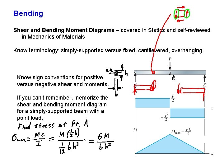
Bending Shear And Bending Moment Diagrams Covered In
0 Response to "38 shear and moment diagram"
Post a Comment