39 oil pressure safety switch wiring diagram
BMW - electrical systems - WIRING DIAGRAM ... Oil pressure switch 13. Temperature transmitter 14. Diagnosis conneclion 15. Engine plug 16. Battery 17. Spark plugs ... Power safety switch 15. Child safety switch 16. Window motor front left 17. Window motor front right 18. Plug for driver's door wire to window motor front left Mar 29, 2021 · master switch 2 block diagram ( left ) /28. pressure sensor pump /87. master switch 2 general layout ( left ) /29. pressure sensor winch 1 /92. master switch 2 supply ( …
Nov 07, 2021 · Cummins isx15 oil pressure problems

Oil pressure safety switch wiring diagram
WIRING DIAGRAM COMPONENT LOCATIONS. When trying to locate a component in a wiring diagram and you don't know the specific system where it is located, use this handy component locator to find the system wiring diagram in which the component is located. Then, go to that system and locate the component within the wiring diagram. Oil Pressure Switch Wiring Diagram – wiring diagram is a simplified all right pictorial representation of an electrical circuit. It shows the components of the circuit as simplified shapes, and the gift and signal friends in the middle of the devices. A wiring diagram usually gives opinion roughly the relative point of view and understanding ... specifications for typical wiring diagram. For external wiring diagrams, see Figs. 4 through 11. For applications using a 208 volt control circuit, it is suggested that one leg of the 208 volt circuit and a neutral or ground wire be used as a 120 volt source to power the time delay heater. When a P28 control is installed on a
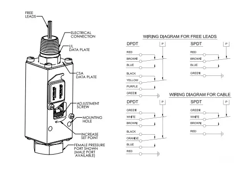
Oil pressure safety switch wiring diagram. Title: P45 Series Typical Wiring Diagrams Illustrating Use of Oil Pressure Cutout Controls Technical Bulletin Created Date: 20180323135817Z This circuit is similar to the basic wiring diagram the same except you use a different pressure switch and add a warning light that directly watches the oil pressure. The 3 Terminal pressure switch has an extra terminal that can be used exactly like the Oil Pressure warning Light. The switch actually is 2 … i have a 87 s10 with a 99 5.7 vortec/ engine harness... The harness was cut when i got it... it came with every other wire just not the 3 wire plug/wiring for the oil pressure sensor... i need to know where the 3 wires go.. the oil pressure sensor is from the 99 5.7 vortec the rest of the harness is finished... anyways the 3 wires are orange, tan and grey... if i member right the oil pressure ... Oil Pressure Switch Wiring Diagram – alco oil pressure switch wiring diagram, danfoss oil pressure switch wiring diagram, engine oil pressure switch wiring diagram, Every electrical arrangement is made up of various distinct parts. Each part ought to be set and linked to other parts in specific way. If not, the arrangement will not function as it ought to be.
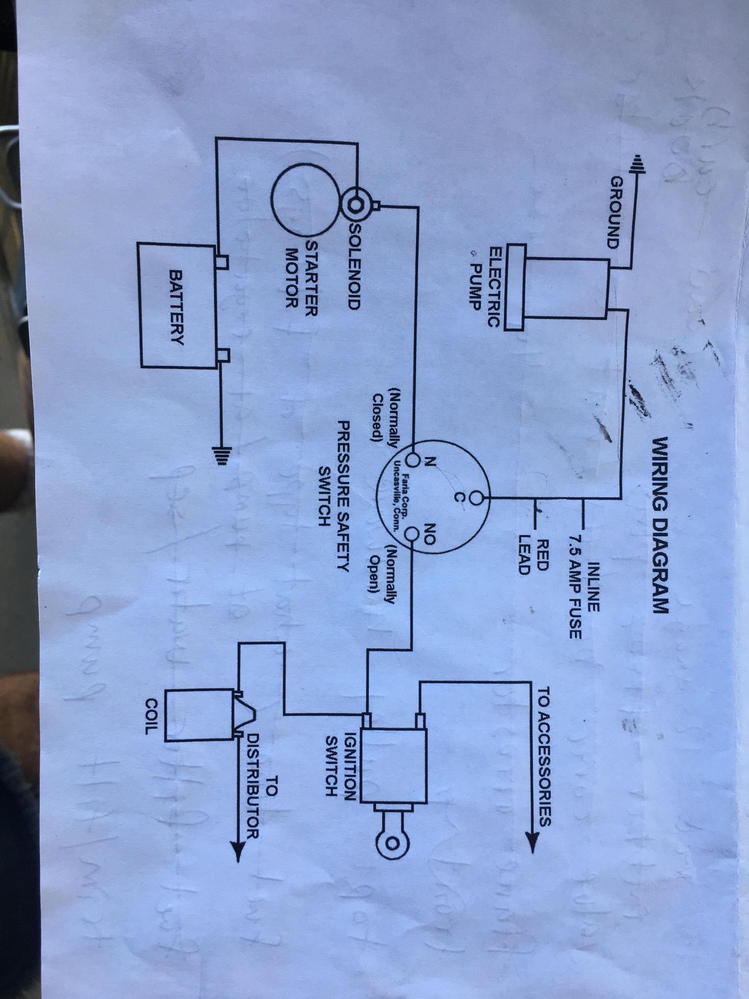
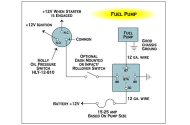
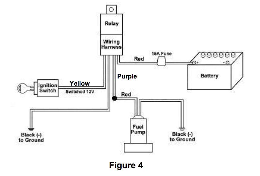
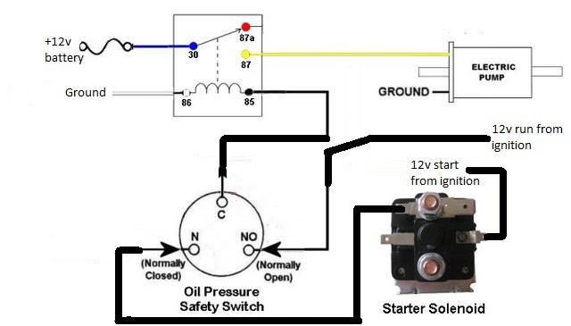
If the oil pressure switch trips it should not be reset or by-passed but the cause for the failure must be found prior to resetting then starting up again. NOTE: Oil pressure safety control with an approved switch is a condition of warranty ! Oil Pressure Differential Normal oil pressure is between 1.05 and 4.2 bar higher than crankcase pressure. How to bypass safety switch on troy bilt riding mower Click upon Set Line Hops in the SmartPanel to show or even hide line hops at crossover points. You can even change the particular size and form of your line hops. Select Show Dimensions to display the length of your wire connections or size regarding your component. Source: Oil Pressure Safety Switch Wiring Diagram. from www.moyermarineforum.com. pressure safety switch in the remaining two holes. 5. Screw in the two switches and reconnect the lead to the original equipment oil pressure switch. NOTE: The pressure safety switch will normally have three terminals marked: C (common), N (normally closed), and NO (normally open). 6. Connect the fuel pump (RED lead) to the terminal marked “C”.
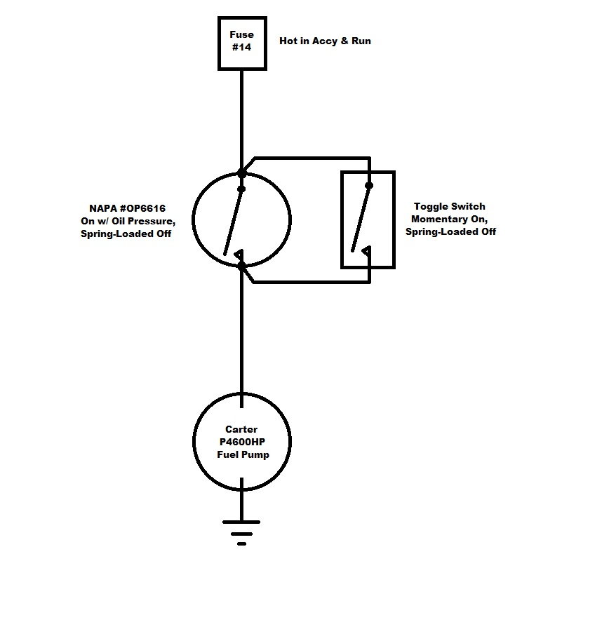
20. Jun 25, 2007. #3. Re: Oil Pressure switch Diagram. see the thing is the guy had it wired to a toggle so you could hold the toggle, prime the pump and fire it up if it sat for a while. well i dont even think the starter solenoid terminal has a wire to the switch on it, and when it died in the water all of a sudden, the two wires i took off ... Wiring Diagram ... The user should plan to acquire and wear safety apparel during operation of this pressure washer. Safety apparel includes waterproof insulated gloves, safety glasses with side and top protection, and non-slip protective ... Pump 13 Pressure Switch 20 Indicator Light 7 Water Inlet (feed tank) (high pressure)14 Water Outlet Today I tried my hand at installing a fuel pump relay and oil pressure safety switch, but didn't quite get the result I'm looking for. The fuel pump isn't supposed to run until the oil pressure sensor hits 5 psi, but right now the pump turns the second I hook the ground cable up on the battery, so obviously I've got my constant wrong, but not sure how to make it all work together. Where is the oil pressure switch on a 1997 Dodge Ram 1500 with a 360 Magnum? 2004 dodge ram 4. If the short is in the wire harness or one of the connectors, repair as needed. need wiring diagram for saturn vue xr 2008, Luciano Santini Ph. 7l Question: AC clutch engaging and disengaging at idle at 10 second intervals with no cooling.
low oil pressure lamp brake warning switch low oil pressure switch ignition switch reverse lights & switch brake lights & switch ammeter heater fan switch + - s ta re battery gauge illumination lamps w1 w2 c1 c2 yp w yg yg b y y n b f r o m f u s e b o x overdrive on - off switch transmission interlock switches pull-in coil cut-out switch ...
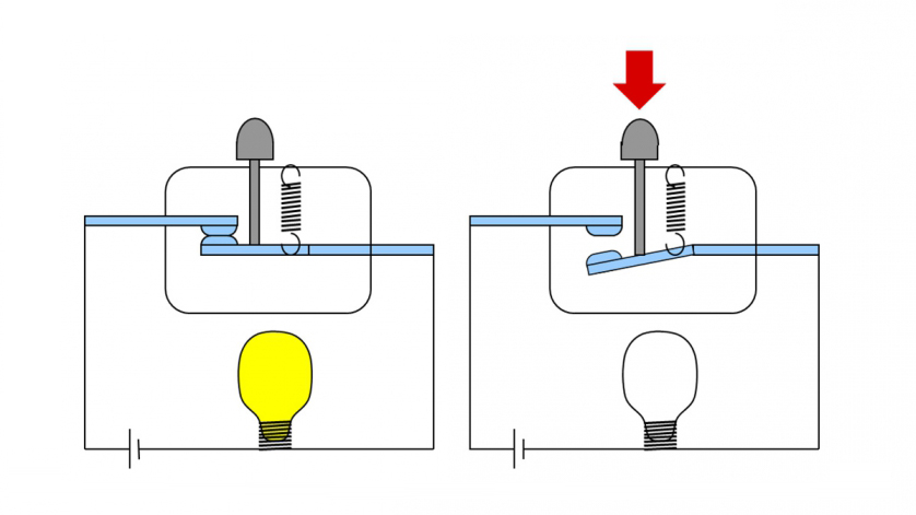
Here, both the pressure switch and the relay contact (CR1-1) are drawn as normally-closed switch contacts. This means the pressure switch contact will be closed when the applied pressure is less than its trip point (50 PSI), and the relay switch contact will be closed when the relay coil is de-energized.

Wiring Diagram Electric Oil Pressure Gauge Inspirationa Ecotec Electrical Diagram Diagram Oil Pressure
specifications for typical wiring diagram. For external wiring diagrams, see Figs. 4 through 11. For applications using a 208 volt control circuit, it is suggested that one leg of the 208 volt circuit and a neutral or ground wire be used as a 120 volt source to power the time delay heater. When a P28 control is installed on a
Oil Pressure Switch Wiring Diagram – wiring diagram is a simplified all right pictorial representation of an electrical circuit. It shows the components of the circuit as simplified shapes, and the gift and signal friends in the middle of the devices. A wiring diagram usually gives opinion roughly the relative point of view and understanding ...
WIRING DIAGRAM COMPONENT LOCATIONS. When trying to locate a component in a wiring diagram and you don't know the specific system where it is located, use this handy component locator to find the system wiring diagram in which the component is located. Then, go to that system and locate the component within the wiring diagram.

2 Prong Oil Pressure Switch Cheaper Than Retail Price Buy Clothing Accessories And Lifestyle Products For Women Men
Oil Pressure Switch Help Please General Discussion Antique Automobile Club Of America Discussion Forums
Oil Safety Switch 3wire Wiring Connections Replacement Moyer Marine Atomic 4 Community Home Of The Afourians









0 Response to "39 oil pressure safety switch wiring diagram"
Post a Comment