40 select the correct shear diagram for the beam
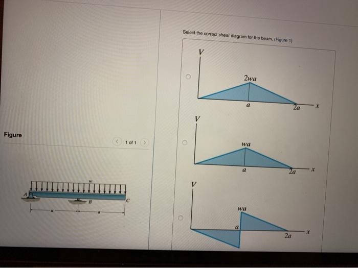
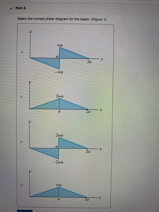
Question: Part A Select the correct shear diagram for the beam (Figure 1) V 2wa o X 2a Figure < 1 of 1 > - Zwa 2wa . Za V wa a 2a -wa V wa x а 2a Part B. Select ... Select the correct shear diagram for the beam figure 1. This is the end of the preview. Draw the moment diagram for 10 points bonus for the beam shown in the figure below draw the shear diagram. Show all your work bonus points. In the figure below block 1 of mass m 1 slides from rest along a frictionl. The intensity of which varies from zero at ...
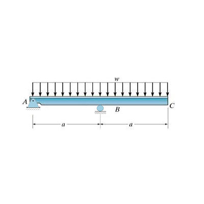
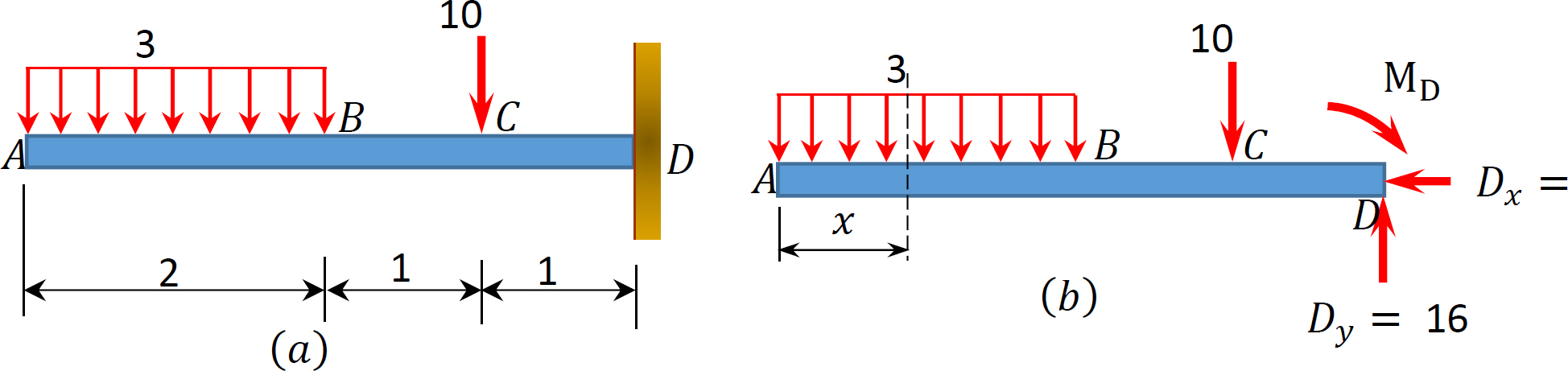
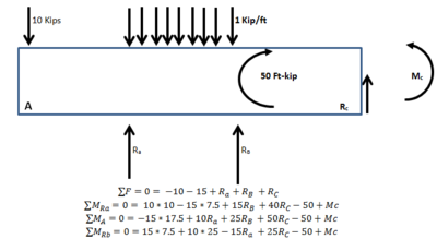
In this particular example, this beam loading-support condition is not part of the table. Therefore, we have no alternative but to use shear and moment diagrams to determine the maximum bending moment in the beam. Steps to draw shear and moment diagrams: 1. Draw a free body diagram of the beam. 2. Determine all the reactions and moments by ...
Select the correct shear diagram for the beam
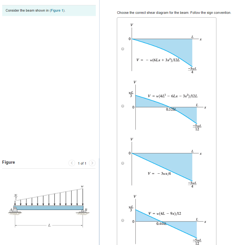
Transcribed image text: Part A Select the correct shear diagram for the beam (Figure 1) V WL * 5L 8 L WL 4 V WL 뿡 X ЗwL. Transcribed image text: Select the correct shear diagram for the beam. 2wa x 2a b) wa a 2a wa MacBook Air a) 2wa X a 2a b) wa a 2a x V wa c) a x 2a - wa V ... 27.10.2021 · Draw the shear and moment diagrams for the beams shown below
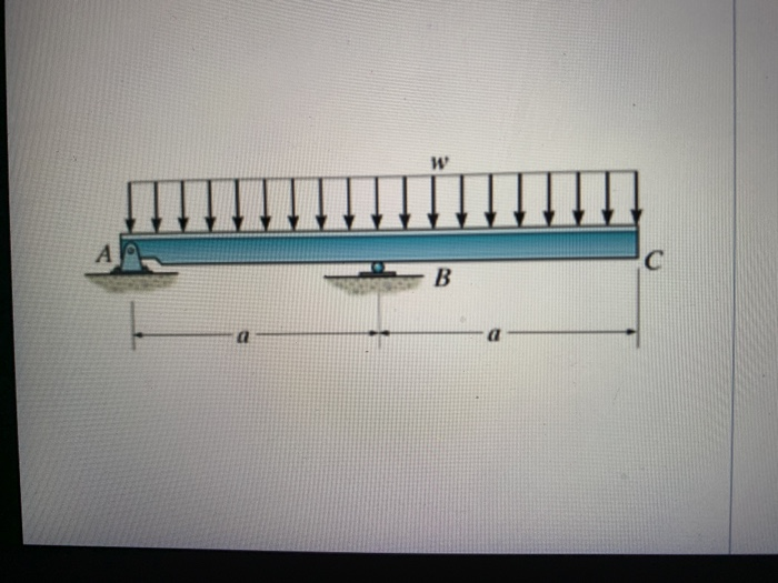
Select the correct shear diagram for the beam. Choose correct short description(s) of a real object for which this would be the correct free-body diagram a. A baseball player sliding into second base. b. A plane slowing down in the air. c. A... Part a draw the shear diagram for the beam. Answer to part a select the correct shear diagram for the beam. Draw the shear and moment diagrams for beam figure 1 posted on march 26 2019 by admin fundamental problem 7 18 add vertical line off segment u roset holp part a draw the shear diagram beams strain stress deflections the beam or flexural ... Once the size of the cross-section of a beam has been determined based on serviceability and strength ... For beams subjected to uniformly distributed gravity loads where the shape of the moment diagram is known, the development lengths in Figure 1 can be used. These recommended details include the requirements for structural integrity reinforcement in ACI 318-14, Section 9.7.7, and can be ... (Figure 1) wa 2a -wa 2wa 2wa x. 2a -2wa wa -Part B Select the correct moment diagram for the beam. 2a 2a 2a 24. This problem has been solved ...
Transcribed image text: Select the correct shear diagram for the beam. (Figure 1) 2wa Figure ( 1011 2wa -2wa Select the correct moment diagram for the beam ... Choose the correct shear diagram for the beam. Follow the sign convention. Choose the correct moment diagram for the beam. Follow the sign convention. Show transcribed image text Expert Answer. Who are the experts? Experts are tested by Chegg as specialists in their subject area. We review their content and use your feedback to keep the quality ... Select the correct shear diagram for the beam figure 1. Solution 43 1 simple beam. This preview has intentionally blurred sections. Shear and bending moment. Shear and bending moment diagrams for beam ab and determine the maximum. As shown in the figure below a uniform beam is supported by a cable at one. Select the correct shear diagram for the beam. As shown in the figure below a uniform beam is supported by a cable at one. In the figure below block 1 of mass m 1 slides from rest along a frictionl. This preview has intentionally blurred sections. From the v diagram the shear force is the same for all cross sections of the beam.
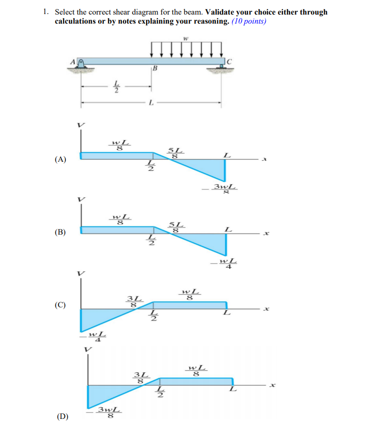
Transcribed image text: Select the correct shear diagram for the beam. (Figure 1) 2wa Figure < 1 of wa 2wa -2wa Submit Request Answer Figure 1 of 1 > Part B ... Select the correct shear diagram for the beam figure 1. Answer to part a identify the shear diagram for the beamfigure 1 identify the shear diagram for the beam. Calculate the shear force at both supports and show the shear force diagram. A beam is shown in the figure below. Academia.edu is a platform for academics to share research papers. Question: 1. Select the correct shear diagram for the beam. Validate your choice either through calculations or by notes explaining your reasoning. (10 points) ...
Select The Correct Shear Diagram For The Beam Figure 1 Study Com
BEAM DIAGRAMS AND FORMULAS Table 3-23 (continued) Shears, Moments and Deflections 13. BEAM FIXED AT ONE END, SUPPORTED AT OTHER-CONCENTRATED LOAD AT CENTER
Web Ncyu Edu Tw
You can select the connector based on simple framing descriptions: You want a Post to Beam connector that matches a doubled 2x6 (about 3" in width) to a 6x6 post top (about 5.5" square) - you'll see connectors labelled accordingly and easier to find than by a manufacturer's part number.
Moment Diagram Beam 35 Images Exercise Shear Bending Moment Diagrams Solution Select The Correct Shear Diagram For The Beam Figure 1 Shear And Bending Moment Diagram For Simply
Indeterminate beam calculator. Homepage. 2. To calculate the limit one needs to know basic rules of limits calculation or use our online Our online calculator is able to find the limits of the wide range expressions. internal forces for indeterminate beams (shear, bending, axial) deflection of the beam due to resulting forces.
Nptel
Beam Calculator Online (Calculate the reactions, Draws Bending Moment, Shear Force, Axial Force) We updated the beam calculator interface and added additional features for calculating beams (calculation of statically indeterminate beams, image saving and section selection)! GO TO NEW INTERFACE (BEAM)>. GO TO NEW INTERFACE (FRAME/TRUSS)>.

Chapter 1 Metallic Implants For Biomedical Applications Rsc Publishing Doi 10 1039 9781788019828 00001
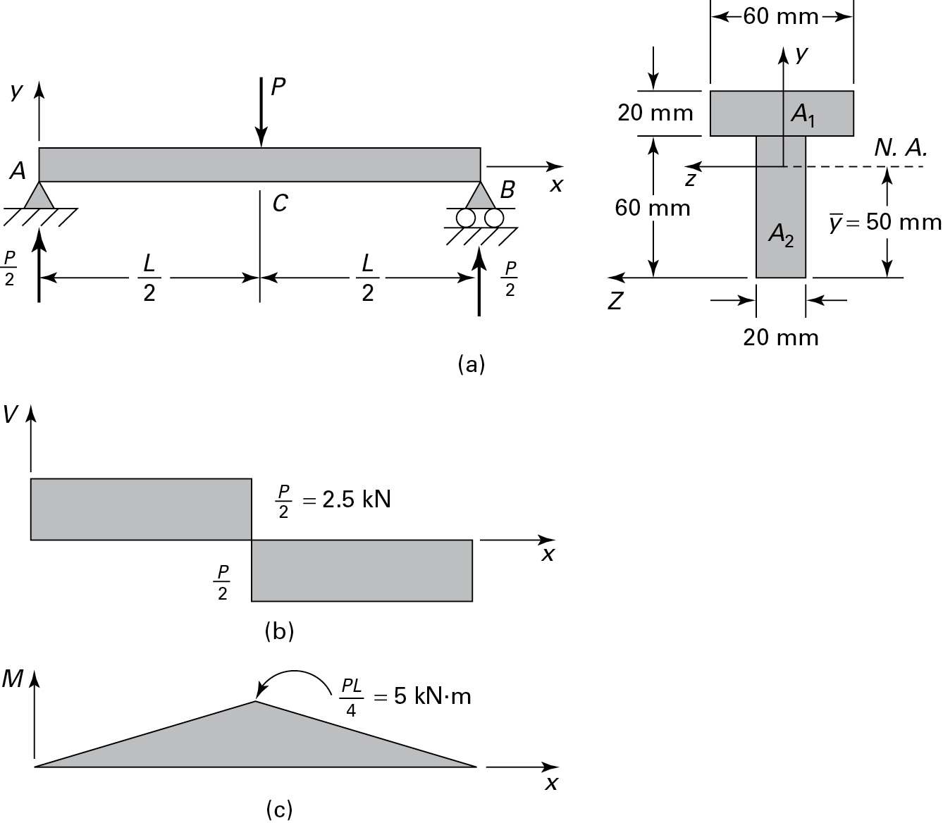
a) Calculate the shear force and bending moment for the beam subjected to a concentrated load as shown in the figure. Then, draw the shear force diagram (SFD) and bending moment diagram (BMD). b) If P = 20 kN and L = 6 m, draw the SFD and BMD for the beam. P kN L/2 L/2 A B EXAMPLE 4

For The Beam Loaded As Shown Which Of The Following Diagrams Correctly Represents The Shape Of Hte Shear Diagram Diagrams Not To Scale Study Com
23.04.2016 · Precast frames can be constructed using either linear elements or spatial beam column sub-assemblages. The use of linear elements generally means placing the connecting faces at the beam-column junctions. The beams can be seated on corbels at the columns, for ease of construction and to aid the shear transfer from the beam to the column. The beam-column joints accomplished in this …
Test Bending Moment Shear Force Diagram 2 30 Questions Mcq Test
Grading policy problem 752 part a select the correct shear diagram for the beam. a) Calculate the shear force and bending moment for the beam subjected to a concentrated load as shown in the figure. We will determine these locations and superimposed on the shear diagram of the beam. Figure 1 draw the moment diagram for the beam. Solution: 700 lb 8 ft 4 ft 6 ft 9400 lb. The shear line will step ...

The Simply Supported Beam Is Supported By Pin Support A And Roller Support C It Is Homeworklib
31.12.2020 · Similarly the shear force diagram, or SFD, displays the value of shear force at any point of the structure while the axial force diagram, or AFD, displays the value of the axial force. In order to construct any of these diagrams, we should preferably know the analytical expression(s) of the corresponding quantity (e.g. the bending moment for the BMD) along the structural member(s).
Solved Draw The Shear And Moment Diagrams For The Beam Shown Below Draw 1 Answer Transtutors
Answer to part a select the correct shear diagram for the beam. 1 simply supported beam with 2 point loads first of all we need to calculate the reactions or shear force at the supports. Part b identify the m. Calculate the shear force at both supports and show the shear force diagram. If you inadvertently place two vertical lines at the same ...
Solved For The Beam And Loading Shown Below A Evaluate Shear Force 1 Answer Transtutors
(Figure 1) w L 3L 8 L wL 4 w L 5L L х 2 wL V w L 5L L х 2 ЗwL V wL 3L ЗwL 8 Select the correct moment diagram for the beam w L2 9WL2 128 16 L 5L 2 8 wL2 5WL2 М ...
1 4 Internal Forces In Beams And Frames Engineering Libretexts
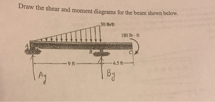
27.10.2021 · Draw the shear and moment diagrams for the beams shown below
Virginiadot Org
Transcribed image text: Select the correct shear diagram for the beam. 2wa x 2a b) wa a 2a wa MacBook Air a) 2wa X a 2a b) wa a 2a x V wa c) a x 2a - wa V ...
Buildings Free Full Text Review Of Push Out And Shear Response Of Hybrid Steel Trussed Concrete Beams Html
Transcribed image text: Part A Select the correct shear diagram for the beam (Figure 1) V WL * 5L 8 L WL 4 V WL 뿡 X ЗwL.
Draw The Shear Diagram For The Beam Home Work Help Learn Cbse Forum
Cmos Camera Beam Profiler
Solved 1 Select The Correct Shear Diagram For The Beam Chegg Com
Tekla Structural Designer 2019i Release Notes Tekla User Assistance
Solved Select The Correct Shear Diagram For The Beam Chegg Com

Multiple Choice Questions Mcq With Answers On Shear Force And Bending Moment Diagram Scholarexpress
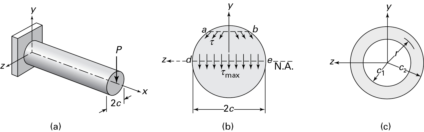
5 7 Normal And Shear Stresses Bending Of Beams Informit
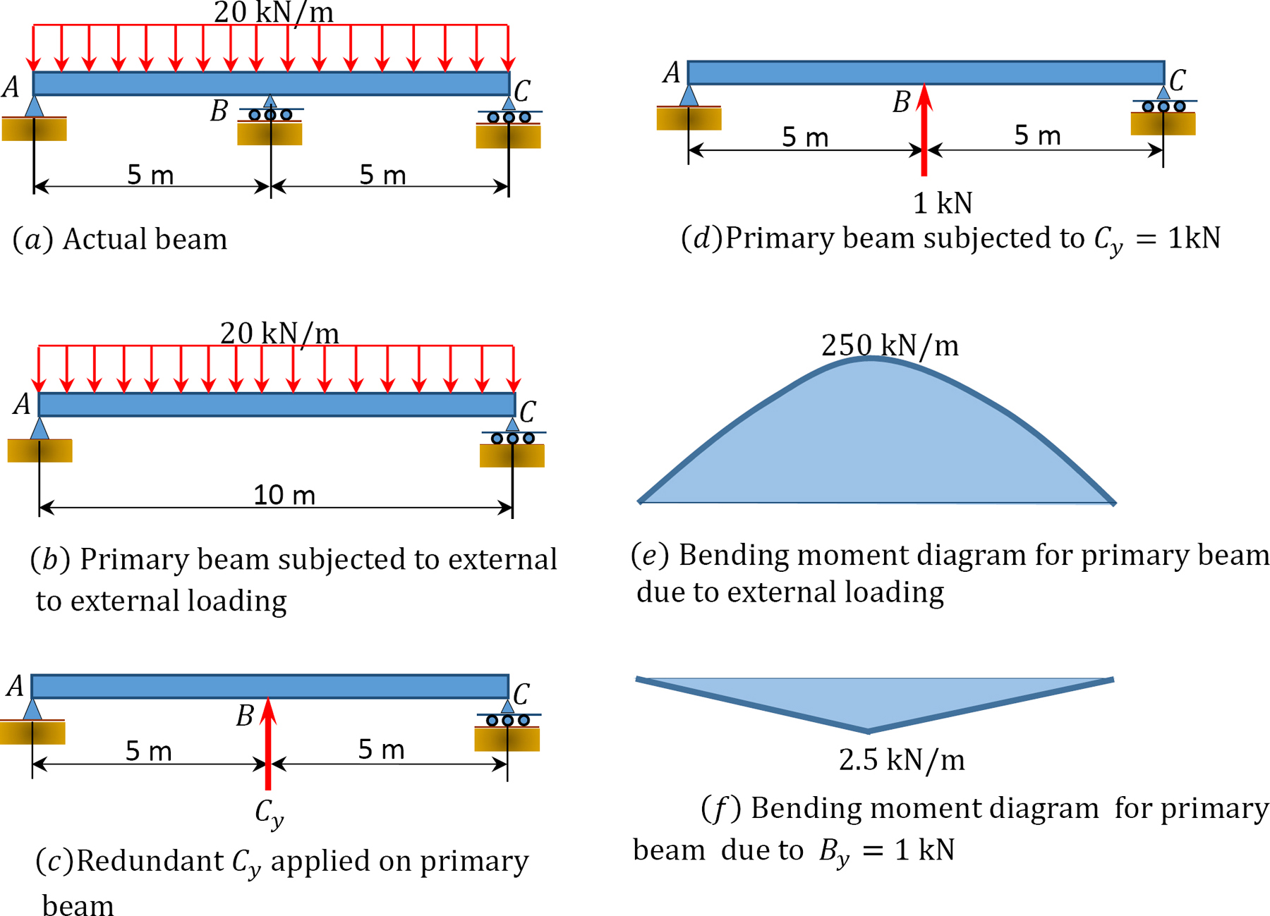
1 10 Force Method Of Analysis Of Indeterminate Structures Engineering Libretexts

A 1 M Long Beam Has A Load Of 5 Kn Applied At Its Center And A Homeworklib
Purdue Edu

Shear And Moment Diagram Wikipedia
5 7 Normal And Shear Stresses Bending Of Beams Informit

Gate Ce 2009 Shear Force And Bending Moment Question 11 Strength Of Materials Or Solid Mechanics Gate Ce Examside Com
Can You Draw The Shear Force And Bending Moment Diagrams Of The Beam Shown In The Figure Below Considering The Given Load Quora
The Ultimate Guide To Shear And Moment Diagrams Degreetutors Com
Solved Part A Select The Correct Shear Diagram For The Chegg Com
Purdue Edu

The Shear Resistance Of A Member Without Shear Reinforcement According To Eurocode 2 The Error Of The Calculated Value And The Mechanical Explanation Of The Problem In International Review Of Applied Sciences
Solved Choose The Correct Shear Diagram For The Beam Follow Chegg Com
Accessengineeringlibrary Com
Profcorey Files Wordpress Com

Mastering Engineering Assignment 12 Beams Engineering Mechanics Statics Assignment12beams Due 11 59pmontuesday April26 2016 Gradingpolicy Course Hero
Solved Part A Select The Correct Shear Diagram For The Chegg Com
Shear And Moment Diagram Wikipedia

Early Breast Cancer Esmo Clinical Practice Guidelines For Diagnosis Treatment And Follow Up Annals Of Oncology
Shear Force And Bending Moment Diagram

Drawing Shear And Moment Diagrams For Beam Youtube
0 Response to "40 select the correct shear diagram for the beam"
Post a Comment