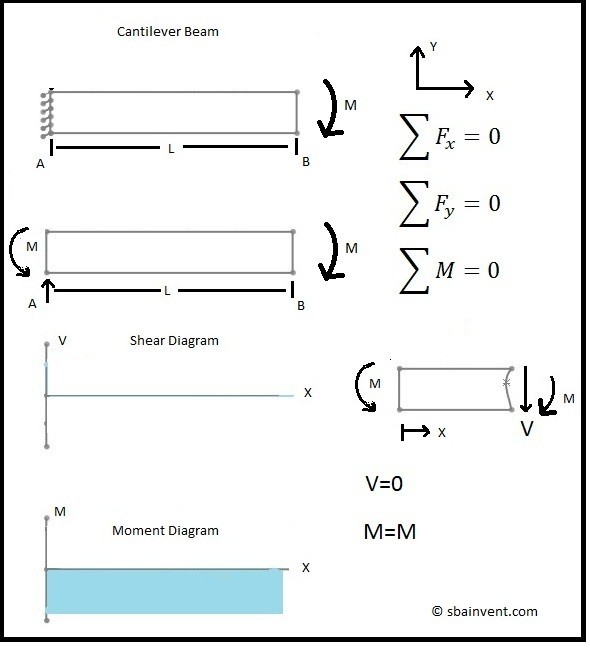
36 moment and shear diagram
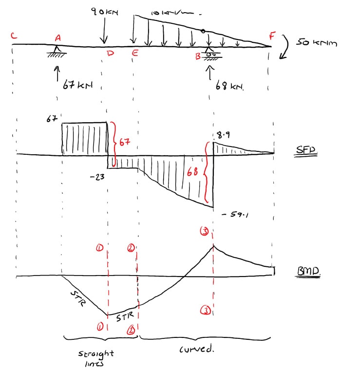
Solve for all external forces and moments, create a free body diagram, and create the shear diagram. Lined up below the shear diagram, draw a set of axes. The x-axis will represent the location (lined up with the shear diagram and free body diagram above), and the y-axis will represent the internal bending moment. Starting at zero at the right side of the plot, you will move to the right, pay attention to shear diagram and the moments in the free body diagram above.
Shear and Moment Equations and Diagrams for Beams H.P. Gavin Spring 2017 1 Shear and Bending Moment Equations 1.Determine all the reactions on the beam. 2.Divide the beam (of length L) into N segments. Segments are separated by: (a)supports (b)external point loads (c)the beginning, end, or change of a load pattern (d)hinges
Welcome to our free online bending moment and shear force diagram calculator which can generate the Reactions, Shear Force Diagrams (SFD) and Bending Moment Diagrams (BMD) of a cantilever beam or simply supported beam.

Moment and shear diagram
Shear and Moment Diagrams for Frames A frame is a structure composed of several members that are either fixed-or pin-connected at their ends. It is often necessary to draw shear and moment diagrams to design frames. Shear and Moment Diagrams for Frames Procedure for analysis-the following is a
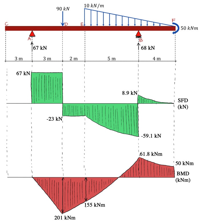
We can combine all this information together to sketch out a qualitative bending moment diagram, based purely on the information encoded in the shear force diagram. Cut 1-1. Taking the sum of the moments about the cut, Repeating this process for cut 2-2, Cut 3-3.
This video is an introduction to shear force and bending moment diagrams.What are Shear Forces and Bending Moments?Shear forces and bending moments are resul...
Moment and shear diagram.
Shear and bending moment diagrams depict the variation of these quantities along the length of the member. Proceeding from one end of the member to the other, sections are passed. After each successive change in loading along the length of the member, a FBD (Free Body Diagram) is drawn to determine the equations express-ing the shear and ...
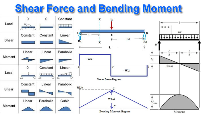
The equation also suggests that the slope of the moment diagram at a particular point is equal to the shear force at that same point. Equation 6.1 suggests the following expression: ΔM = ∫ V (x)dx Δ M = ∫ V ( x) d x (Equation 6.2) Equation 6.2 states that the change in moment equals the area under the shear diagram.
a Shear and Moment Diagram : Constructing shear and moment diagrams is similar to finding the shear and moment at a particular point on a beam structure. However, instead of using an exact location, the location is a variable distance 'x'. This allows the shear and moment to be a function of the distance, x.
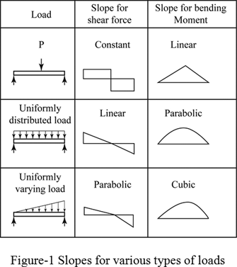
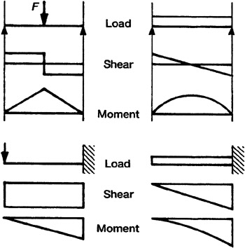
4.4 Area Method for Drawing Shear- Moment Diagrams Useful relationships between the loading, shear force, and bending moment can be derived from the equilibrium equations. These relationships enable us to plot the shear force diagram directly from the load diagram, and then construct the bending moment diagram from the shear force diagram.
Shear and bending moment diagrams are analytical tools used in conjunction with structural analysis to help perform structural design by determining the value of shear force and bending moment at a given point of a structural element such as a beam. These diagrams can be used to easily determine the type, size, and material of a member in a structure so that a given set of loads can be supported without structural failure. Another application of shear and moment diagrams is that the deflection o
Problem 403 Beam loaded as shown in Fig. P-403. [collapse collapsed title="Click here to read or hide the general instruction"]Write shear and moment equations for the beams in the following problems. In each problem, let x be the distance measured from left end of the beam. Also, draw shear and moment diagrams, specifying values at all change of loading positions and at
Shear and Moment Diagrams If the variation of V and M are written as functions of position, x, and plotted, the resulting graphs are called the shear diagram and the moment diagram. Developing the shear and moment functions for complex beams can be quite tedious.
Jan 06, 2005 · Shear and moment diagrams and formulas are excerpted from the Western Woods Use Book, 4th edition, and are provided herein as a courtesy of Western Wood Products Association. Introduction Notations Relative to “Shear and Moment Diagrams” E = modulus of elasticity, psi I = moment of inertia, in.4 L = span length of the bending member, ft.
What are the benefits of drawing shear force and bending moment diagram? The benefits of drawing a variation of shear force and bending moment in a beam as a function of 'x' measured from one end of the beam is that it becomes easier to determine the maximum absolute value of shear force and bending moment.
If the shear diagram is a parabola, the moment diagram will be a cubic. 4) You can tell if a triangular shear diagram should "turn into" a "skinny" parabola or a "fat" parabola by using the calculus: The value at any point on any diagram "turns into" (integrates into) the slope of the next diagram.
Being able to draw shear force diagrams (SFD) and bending moment diagrams (BMD) is a critical skill for any student studying statics, mechanics of materials, or structural engineering. There is a long way and a quick way to do them. The long way is more comprehensive, and generates expressions for internal shear and internal bending moment in ...
BEAM DIAGRAMS AND FORMULAS Table 3-23 (continued) Shears, Moments and Deflections 13. BEAM FIXED AT ONE END, SUPPORTED AT OTHER-CONCENTRATED LOAD AT CENTER
Calculate the shear force and bending moment for the beam subjected to a concentrated load, then draw the shear force diagram (SFD) and bending moment diagram (BMD). Answer: By taking the moment at A, MA = 0 - RBy × 5 + 15 × 3 = 0 RBy = 9 kN Fy = 0 RAy + RBy = 15 RAy = 15 - 9 RAy = 6 kN Fx = 0 , RAx = 0 Shear force and bending moment diagram
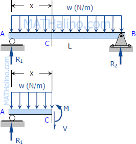
Shear and Moment Diagrams Shear and Moment Diagrams Consider a simple beam shown of length L that carries a uniform load of w (N/m) throughout its length and is held in equilibrium by reactions R 1 and R 2. Assume that the beam is cut at point C a distance of x from he left support and the portion of the beam to the right of C be removed.
Setting the bending diagrams of beam. Calculate the reactions at the supports of a beam. Bending moment diagram (BMD) Shear force diagram (SFD) Axial force diagram. Invert Diagram of Moment (BMD) - Moment is positive, when tension at the bottom of the beam.
Jul 23, 2021 · 4.0 Building Shear and Moment Diagrams. In the last section we worked out how to evaluate the internal shear force and bending moment at a discrete location using imaginary cuts. But to draw a shear force and bending moment diagram, we need to know how these values change across the structure.
Bending moment and shear force diagram calculator Language: ENGLISH / ESPAÑOL Distance Units: METER / FEET Force Units: kN / kgf / lbf / kip Bending moment and shear force diagram calculator, it generates the Reactions for the supports and draws the SFD (Shear Force Diagram) and BMD (Bending Moment Diagram) of a simply supported beam.
Draw the moment diagram below the shear diagram. load is the slope of the moment and point moments result in jumps in the moment diagram. The area under the shear diagram equals the change in moment over the segment considered (up to any jumps due to point moments). Label the value of the moment at all important points on the moment diagram.
PDF_C8_b (Shear Forces and Bending Moments in Beams) Q6: A simply supported beam with a triangularly distributed downward load is shown in Fig. Calculate reaction; draw shear force diagram; find location of V=0; calculate maximum moment, and draw the moment diagram. 6k/ft 9 ft RA = (27k)(9-6)/9= 9k A B F = (0.5x6x9) = 27k x = (2/3)(9) = 6 ft
Dr. M.E. Haque, P.E. Beam Reactions, Shear and Moment (Page 7 of 12) w L Sym. 2 / 8 - w x2 /2 w x2 /2 P 1 L / 4 P 2 x w L / 2 + P 1 / 2 MOMENT DIAGRAMS Fig. 1 Fig. 2 Fig. 3 Algebraic summation of coordinates of these three moment diagrams will produce the final moment diagram.
M = Fd = 0. Fy = 0. Part of a project I am working on (part #3…see description below) is asking us to find the internal loads (shear and moment) and draw the corresponding shear/moment diagrams of the control arm shown below. It's a little tricky to me, because all of the members associated with these type of problems are normally straight ...
This video explains how to draw shear force diagram and bending moment diagram with easy steps for a simply supported beam loaded with a concentrated load. S...
3.2 - Shear Force & Bending Moment Diagrams What if we sectioned the beam and exposed internal forces and moments. This exposes the internal Normal Force Shear Force Bending Moment ! What if we performed many section at ifferent values Of x, we will be able to plot the internal forces and bending moments, N(x), V(x), M(x) as a function Of position!




![10] shear force diagram & bending moment diagram](https://image.slidesharecdn.com/10shearforcediagrambendingmomentdiagram-120404040042-phpapp01/95/10-shear-force-diagram-bending-moment-diagram-11-728.jpg?cb=1333512735)
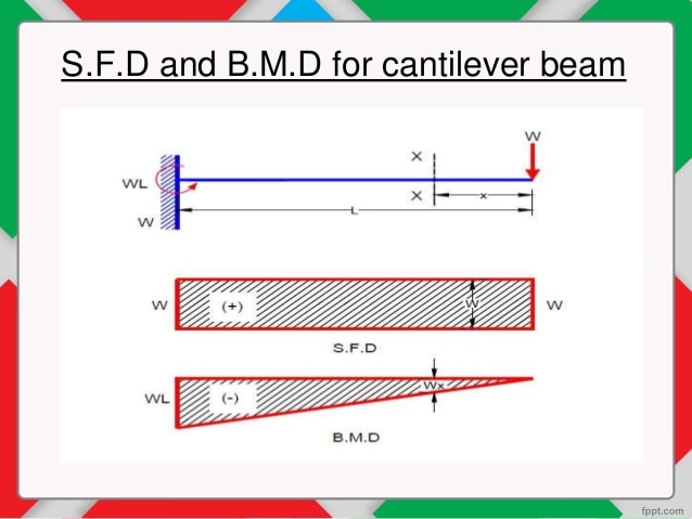







![10] shear force diagram & bending moment diagram](https://image.slidesharecdn.com/10shearforcediagrambendingmomentdiagram-120404040042-phpapp01/95/10-shear-force-diagram-bending-moment-diagram-8-728.jpg?cb=1333512735)

0 Response to "36 moment and shear diagram"
Post a Comment