36 motorola cdm1250 wiring diagram
MOTOROLA CDM RADIO INTERFACE CABLE TO IP-223 8/6/2013 Dave Grant The color code for the DB25-DB25 cable that is included with the IP-223 has changed. This interface spec is to call out the differences and provide an updated wiring diagram. This appnote should be used in conjunction with Telex CDM radio guide AN-DISPATCH-009-CDM-GM-PRO.pdf.
Motorola Programming Cable Pinouts. HERE THEY ARE, ALL THE PINOUTS YOU NEED!! If you've got one that isn't here, email us the info and we'll add it to the list! RIB/Computer Related Cables. RIB TO IBM PC (25 PIN) RIB TO IBM PC (9 PIN) Polaris RIB Cable Pinouts. FlashPort SmartRib to IBM PC. RIB to Hand Held Radio Cables.
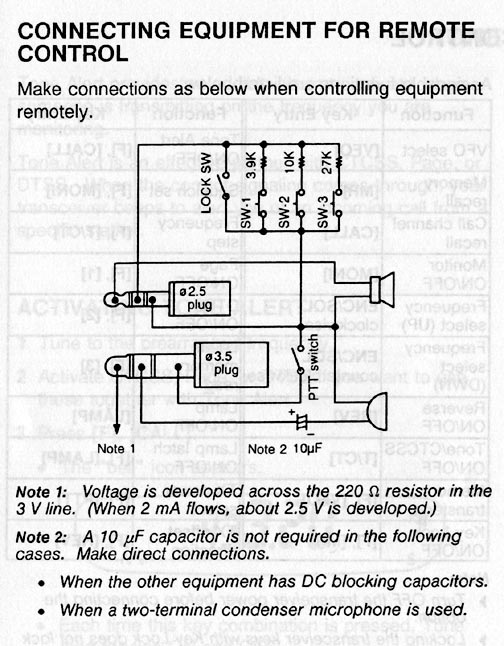
If you figure out how to do this, let me know. Motorola seems to have put a little effort into making their mics incompatible with other equipment. There are three problems with getting this to work on another radio. The mic is powered by the radio. To complicated issues, this power is the current flowing through the closed TX connections.

Motorola cdm1250 wiring diagram
39 motorola cdm1250 wiring diagram; 39 g35 bose amp wiring diagram; 38 ttr 90 carb diagram; 41 sno pro 3000 wiring diagram; 39 semi automatic pistol diagram; 42 washing machine plumbing diagram; 37 cordless drill battery charger circuit diagram; 39 2003 nissan xterra engine diagram; 38 westerbeke generator parts diagram; 40 nema 10 50r wiring ...
2,730. Location. Northville, NY (Fulton County) May 4, 2021. #2. Pins 1-8 are the same as Maxtrac and similar. Pins 9 and 10 are DTMF control lines and only used with AANRMN4026 mics. You can safely use Motorola hand and desk mics from Radius, Commercial, Maxtrac and similar. Last edited: May 4, 2021.
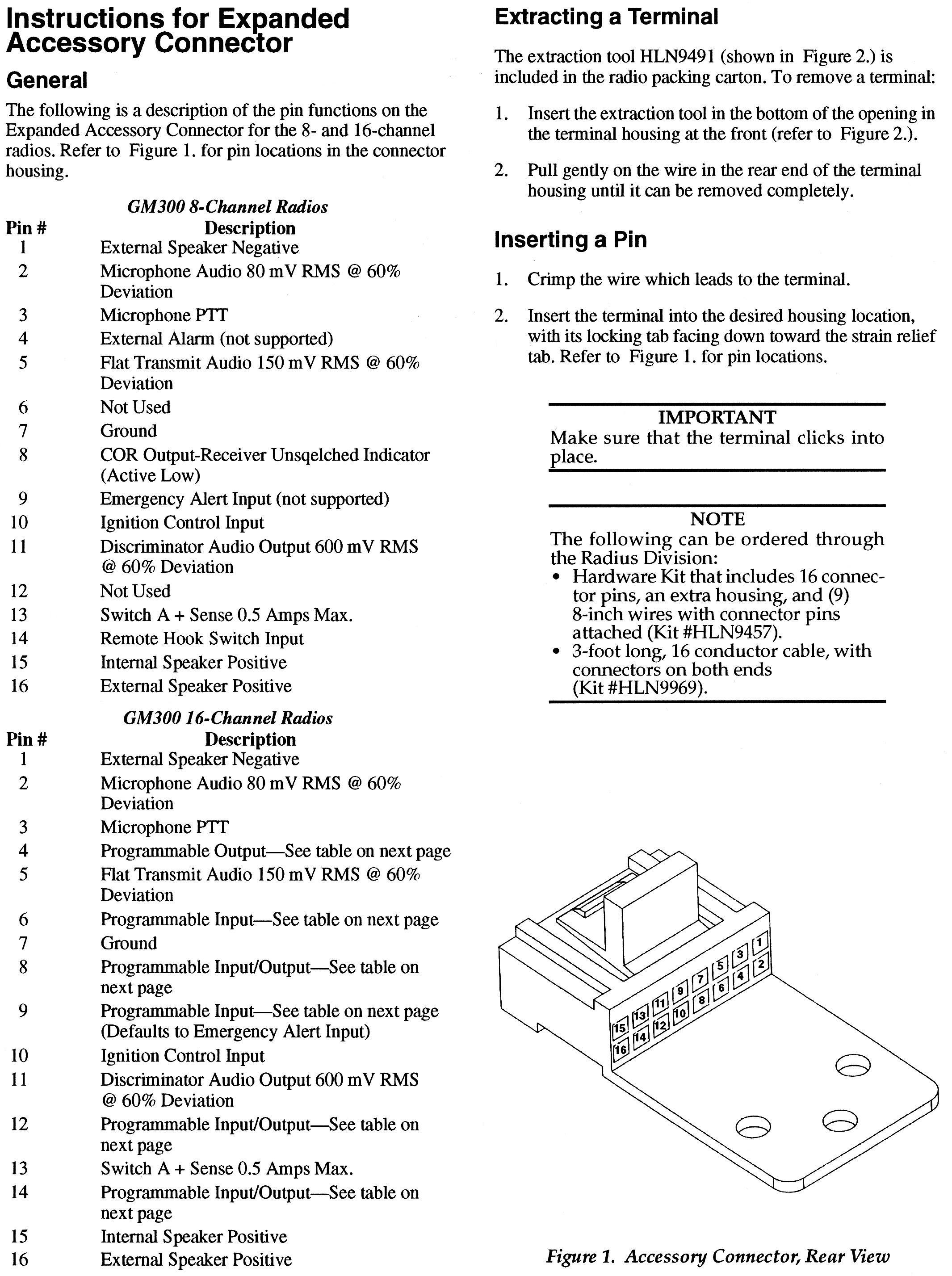
The connector/pinout information may be applied to the Motorola model CDM1250 There is one pinout found for Motorola CDM1250 . The pinout (pin-out) is a cross-reference between the contacts (pins) of an electrical connector and their functions. The pin assignment diagram is listed below. Click for details
Motorola cdm1250 wiring diagram.
To obtain Motorola software see the Sticky in the Motorola forum. ... Cable 35 External Speaker Motorola CDM CDM1250 VHF UHF | eBay ... Also, as far as a diagram for the CDM radio wiring and accessory connector, the basic service manual is floating around on the web as a .pdf file. It is the best source of this info.
User Manual (PDF) .... 8 hours ago — ... 1992 Chrysler Corporation Ford Motorpany Wiring Diagram Manual Motor ... Satis Electrical Wiring Diagram Ewd Workshop Repair Service Manual En Fr ... Volvo V70 Electrical Diagram - Motorola Cdm1250 Pin Diagram - 12 Volt ...
See section 11.9 of the Motorola R56-Standards and Guidelines for Communications Sites for more detailed information. Table 1. Other Documentations Information Location CDM-Series Operation (North America) CDM750 User Guide (6881091C54) CDM1250 User Guide (6881091C55) CDM1550 User Guide (6881091C56) CDM-Series Programming (North America) CDM ...
Motorola Cdm1250 Wiring Diagram. motorola gm300 radios programming cable motorola radio gp350 gm300 maxtrac radius cdm1250 cp200 m1225 ebay 8 moleculo jun 19 2014 moleculo administrator, to obtain motorola software see the sticky in the motorola forum the cdm s and many of the older radius s and m1225 s are all wired.
post on the CDM1250 figured out (i think) but cannot locate the diagram for the mic itself. For your consideration, here is a Motorola AARMN4025B standard palm mic. On my CDM1250, when pin 7 is jumpered to pin 9 and power is applied to the radio, the radio turns on automatically.
The Motorola products described in this manual may include copyrighted Motorola computer programs stored in semiconductor memories or other media. Laws in the United States and other countries preserve for Motorola certain exclusive rights for copyrighted computer programs, including, but not limited to, the exclusive right to copy or
6, @DW4CHZ maxtrac motorola ,two radio are working good without any adjustment on board 7, @BI7JTA CDM1250 /CDM1550/GM338 need to do: 1) Re program radio follow user guide, 2) Change pi-star config TXInvert=0 8, @F4HES GM340 TXInvert=0 9, @DW7FCV ICOM ID-4100 DStar bandwidth to narrow 12.5KHz 10, @IW6BFE MTR2000 add 22uF capacitor to TX, view the end part of this blog
Motorola CDM Series of Professional Mobile Two-way Radios: CDM750, CDM1250, CDM1550, CDM1550.LS+ Motorola Two-way Radio Product Transitions Updated 2014/11/14 | PDF 405.24KB
READ Motorola Cdm1250 Wiring Diagram Database. 2002 Grand Prix Wiring Diagram Source: i1.wp.com 2002 Grand Prix Wiring Diagram Source: i.pinimg.com. READ Reliance Brake Controller Wiring Diagram Database. Before reading the schematic, get common and understand each of the symbols. Read the particular schematic like a new roadmap.
Wiring Diagram Subaru Impreza 2015 - Bolens 1225 Wiring Diagram - 06 ... 1995 Chevy Blazer Radio Wiring Diagram - 12v Relay Switch Wiring .... Aug 15, 2013 — Hello guy's i am the owner of a Motorola m 1225
CDM1250 TM Série Professionnelle Radio Mobile Guide de l´usager Professional Series Mobile Radio User Guide PMS 1807 CMYK = 0, 100, 96, 28 CDM1250
PolarisUSA is proud to offer Motorola Radio Programming Cables. This USB "RIB-less" cable Programs the Motorola Models CDM750, CDM1250, CDM1550, CDM1550LS, CDM1550LS+, CM200, CM300, EM200, EM300, GM300, LCS2000, LTS2000, M10, M120, M130, M1225, Maratrac, Maxtrac, PM400, SM50, SM120 Please note: This cable can be connected directly to your computer without the use of a Programming Adapter.
Honghuismart mic speaker handsfree 8 pin untuk motorola gm338, gm950, gm300, gm3188, gm3189, gm3689, gm340 mobil dll dasar radio untuk taksi
The Motorola products described in this manual may include copyrighted Motorola computer programs stored in semiconductor memories or other media. Laws in the United States and other countries preserve for Motorola certain exclusive rights for copyrighted computer programs, including, but not limited to, the
Motorola maxtrac gm300/m120
This is the manuals page for Motorola. In this page you find schematic, users and instructions manuals, service manuals, technical supplement, leaf leads and other good stuff. If you have some stuff that not is listed here you can donate this by contact mods.dk. Note that there is a limit to the number of files you can download.

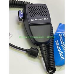
Cable kit # 97 remote mic mike extension motorola cdm cdm750 ...
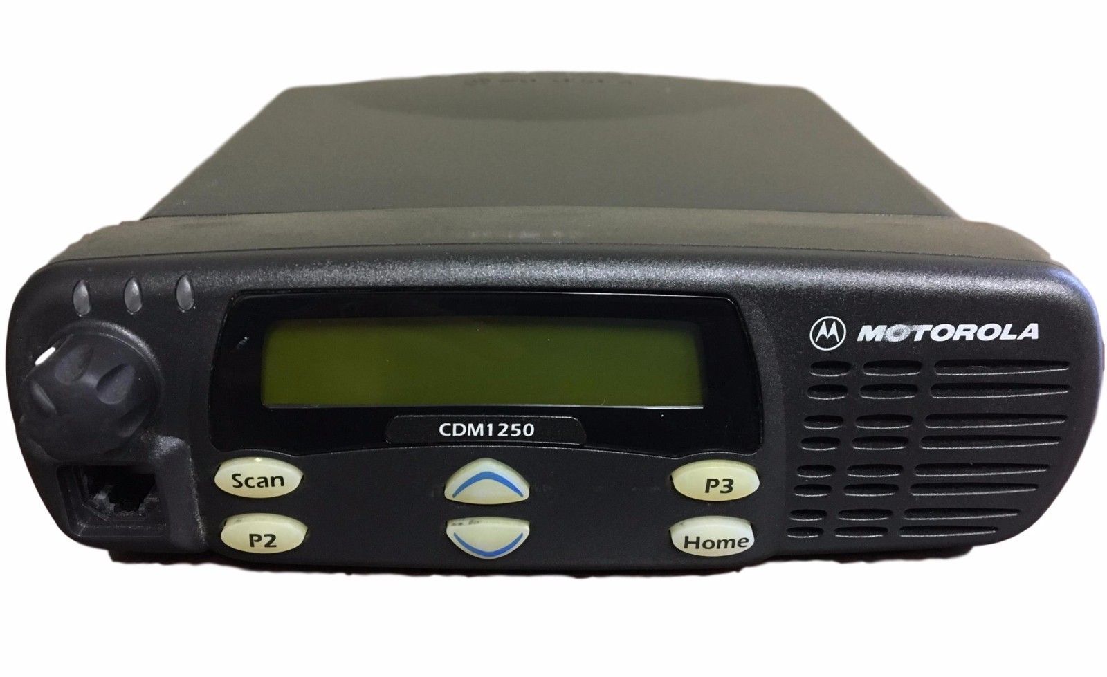
MOTOROLA UHF CDM 1250 Radios· 403-470 MHz/ 64 Channel/ 40 Watts· 16 Pin accessory port· Tested by an authorized Motorola Technician and is 100% good working order· Mics. Brackets, power cables and all other accessories available upon request at additional cost FREE PROGRAMMING UP TO 16 CHANNELS 1-888-968-9693.
Date
Yaesu FT-840 uses the circular 8-pin CBC connector, an adapter cable would need to be built. ==. The Motorola HMN3000 (B) models has been discontinued, and replaced by the RMN5068A desk microphone. So, you will find this model at Rallies, Hamfests, Surplus equipment sales, & eBay. KNOCK-OFF copies of this microphone exist (and sold) in Eastern ...

Motorola
41 orbital diagram for titanium. Written By Stephan T. Hawkins Thursday, November 18, 2021 Add Comment. Edit. The electron configuration for titanium is 1s22s22p63s23p63d24s2, according to the Jefferson Lab website. The element's 22 electrons are arranged in four energy levels surrounding the nucleus of the atom.
99ft4092 2-way mobile radio user manual installation guide ...
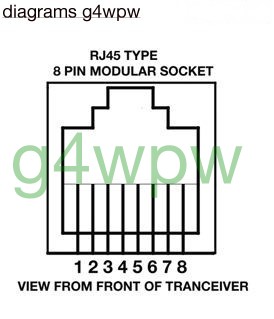
'motorola radius pinout diagram pinouts ru april 29th, 2018 - pinout of motorola radius and layout of 8 pin rj45 8p8c female connectormic conector for sm50 gm300 p1225' 'rmn5068 desktop mic for motorola cdm1250 alibaba com april 26th, 2018 - rmn5068 desktop mic for motorola cdm1250 cdm1550 cdm750 lcs2000 max trac mcs2000 find complete details ...
Gm300 information page
Simplex and Repeater diagram (Motorola 16 Pins and 20 Pins) Duplex/Repeater Mode Connection Simplex Mode(Hotspot) Connection ... The pinout and data define same as GM338/CDM1250/1550 Data radio FC302. MTR2000 Motorola. Share by @IW6BFE Arrio , verified by @BI7JTA Pi-Star settings: [Modem] Port=/dev/ttyAMA0 TXInvert=0 RXInvert=0 PTTInvert=0 ...

Motorola cdm1250 @ pinouts.ru
Vsm 900 Turn Signal Wiring Diagram; Motorola Cdm1250 Wiring Diagram; 1993 Fxdl Wiring Diagram; Motorcraft 2150 Carburetor Diagram; 2002 Dodge Caravan 3.3 Serpentine Belt Diagram; Yamaha Cpx 15w Wiring Diagram; Squirrel Cage Fan Wiring Diagram; Three Element Oven Single Phase /wiring Diagram; Everglades Food Web Diagram; 95 Yamaha Big Bear 350 ...
Date
If you want the radio to come on when you start the car, run your main power cable hot to the battery and ground to a factory grounding point. Then take run/accessory +12v and run it to pin 10 on the accessory port. The 7/9 shorting trick requires 9 to be properly programmed. It works on some radios and not on others.
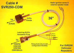
Pyramid repeater cable svr250 - cdm motorola cdm750 cdm1250 ...
Motorola Cdm1250 Wiring Diagram. Here are pinouts for Motorola CDM devices. The link to appropriate pin assignment diagram is listed below. Accesories for Radios SMGM pinout . The Motorola products described in this manual contain one or more computer CDM, CDM, or CDM mobile radios. Station I/O schematic.

Hkn9327br ignition switch cable

Motorola visar programming software - roombrands

Cat repeater controller cable motorola cdm cdm1250 cm300 gm300 ...

Motorola cdm1250 radio review|| motorola mototrbo mobile radios ...
92ft4859 mobile and base station transmitter user manual cdm1250 ...
92ft4859 mobile and base station transmitter user manual cdm1250 ...

Cable 93 motorola cdm cdm1250 cdm1550 vhf uhf repeater walkie ...

Cdm flash adapter
Jual gm3188 murah & terbaik - harga terbaru july 2021
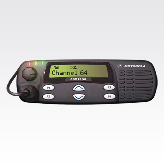
Motorola cdm1250 mobile two-way radio - motorola solutions

Motorola
Motorola cdm1250 | jeffrey kopcak, mba – k8jtk
Kabel data sata internal pc cable hardisk dvd rw rom komputer hdd ...
Gm300 information page

Mmdvm repeater @bi7jta: configure guide for mmdvm repeater kit ...
Bi7jta's wiki for mmdvm

Jual motorola radio di tangerang - harga terbaru 2021

Ignition wire kit for motorola mobiles cdm750 cdm1250 m1225 cm300 cm300d pm400 | ebay
Waris - w9cr

Motorola programming cable cdm1250 m1225 cdm1550 cdm750 | ebay
Motorola cdm1250 mobile two-way radio - motorola solutions
Date

Motorola

Motorola cdm1250, cdm750, pro5100, pro3100, pro7100 service manual ...

Motorola
0 Response to "36 motorola cdm1250 wiring diagram"
Post a Comment