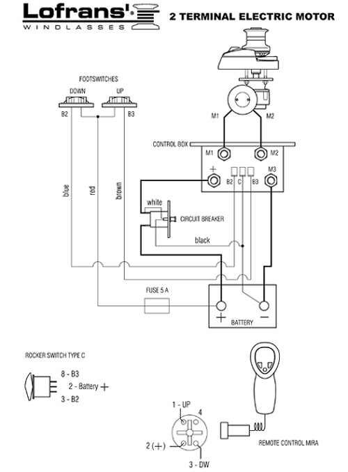
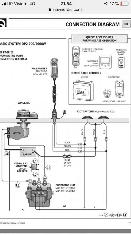
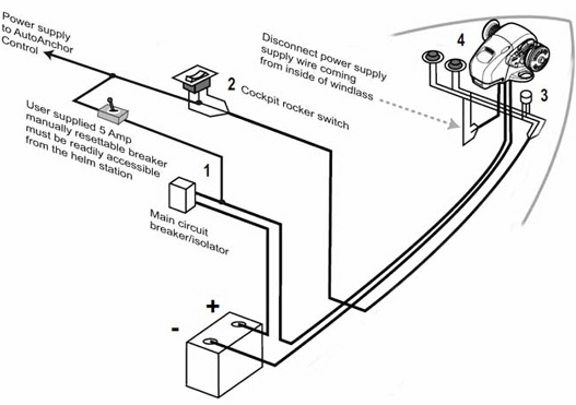
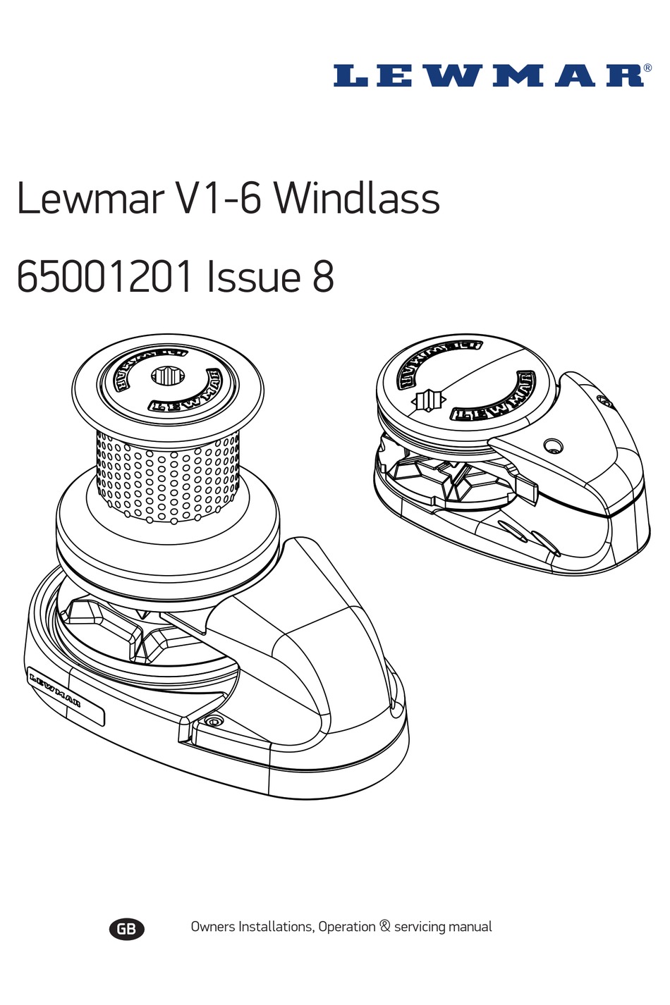
37 lewmar windlass wiring diagram
4. Electrical Wiring 12 4.1 Electric cable selection 12 4.2 Wiring 12 4.3 Control switch installation 13 4.4 Pro wiring diagram with contactor 14 4.5 Pro wiring diagram with contactor box 15 4.6 Pro wiring diagram with pre-wired control box 16 5. Operation 17 5.1 Pro-Fish braked anchor freefall 17 5.2 Pro-Series/Sport braked anchor freefall 18
Can be used with all Lewmar custom windlasses, contact the sales office for a specific wiring diagram. Sprint 900, Atlantic, Atlantic A, Atlantic C, AP700, AP1000 & AP1200 : Use Diagrams A* or B Atlantic B & Concept / Ocean2 : Use Diagrams C or D - Sprint 3000 : Use Diagrams C or E *Contactor 0052531 is NOT suitable for these products.
This will bypass both the switch and solenoid wiring the windlass motor directly to the power source. Do this for troubleshooting only to test that the solenoid is the only problem. Step 3: Use a voltmeter to check for voltage at the windlass motor. Put the positive probe on the electrical stud on the motor, the negative probe on

Lewmar windlass wiring diagram
Wiring • Plan wiring installation to suit controls and to give operator full view of windlass. • Use marine grade copper wire. • Fit copper crimp terminals to wire ends. • Keep windlass wiring separate from other wiring, and connect to starter battery where possible. • The circuit breaker must be kept dry. • All switches must be ...
Lewmar v700 2. Electrical wiring installation . 6V700 Windlass 7, 2. Electrical wiring installation, +, E, A, 2.1 Electric cable selection, 2.2 Wiring, 2.3 Control switch installat ion, 2.4 V700 Wiring diagram (t oggle switch), 3.1 Safety rst, 3.2 Use of clutch, 3.3 Letting go under grav ity
About Press Copyright Contact us Creators Advertise Developers Terms Privacy Policy & Safety How YouTube works Test new features Press Copyright Contact us Creators ...
Lewmar windlass wiring diagram.
Sep 14, 2018 · 1. 2. GREY. BLUE. Lewmar windlasses are designed and supplied for anchor control in marine applications and are not to be . Wiring diagram using contactor provided ( Part No ) .. Is there voltage at the positive switch terminal on the solenoid. If your windlass is reversing it simply has an additional footswitch, solenoid .
Lewmar Windlass Wiring Diagram. Lewmar Wiring Diagram Wiring Diagram Third Level 66840008 Lewmar Bow Roller For Delta Type Anchors 14lb To 35lb Lewmar Windlass V700 Kit 1 4 In G4 Chain Rope Gypsy 12v Vertical Windlass Diagram Courtesy Of Lewmar This Diagram Vetus Bow Thruster Control Wiring Diagram 2014 Lexus Is 250.
Gx Series Anchor Winch Drum Acc Wiring Loom Up To 8mtr Smart Marine. How to choose the right windlass maxwell muir vrc1250 anchor winch cruisers electrical problem cable sizing for power wiring sailboat owners ideal cwm upgrade trawler forum 500w 12v vertical electric winches q and a from harken converting up down user manual installation guide your boat rc12 lewmar profish 1000 free fall drum ...
Looking at Ralph wire diagram, it looks like he tapped off from the main power cable. Actually, that is the wiring diagram from the Lewmar installation instructions. Here's my as-built wiring. Seeing as I already had a 5A breaker for the windlass on my panel, I thought I'd use it as a...
The wiring diagram that came with it is very generic and I.The original Windlass since Italian engineering and design. Apr 19, · As can be seen when comparing this video to the first video titled "Lofrans Tigres Horizontal windlass problems" The motor is running fast and strong.
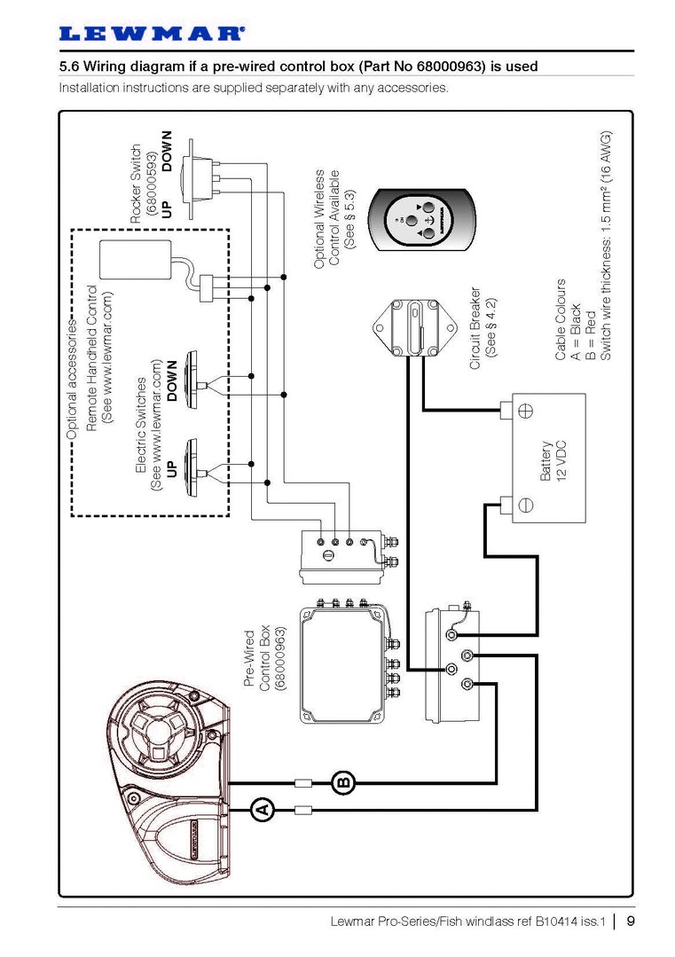
Lewmar Pro-Series/Fish windlass ref B iss.1 Page 8. Wiring diagram if a contactor box (Part No ) is used Installation instructions are supplied separately with any accessories. Page 9. Wiring diagram if a pre-wired control box (Part No ) is used Installation instructions are supplied separately with any accessories. Lewmar Windlasses.
Lewmar V700 Vertical Windlass ref 65001022 iss.8 | 7 CABLE SIZING FOR LENGTH OF CABLE RUN 0 - 10 m 0 - 33 ft 11 - 18 m 34 - 60 ft 19 - 24 m 61 - 80 ft 10 mm2 8 AWG 16 mm2 6 AWG 25 mm2 4 AWG 5. Electrical wiring 5.1 Electric cable selection Plan the installation to suit the controls and give the operator a full view of the windlass. The wiring ...
Nov 16, 2018 · Nov 02, · Windlass is Simpson Lawrance sprint (Old but unused) Manual states windlass is Power reversing. Contactor is Lewmar marked as dual direction with terminals as described i.e only 3 battery connection posts (large brass ones). Marked F1, F2 & Batt +. Wiring diagram for windlass shows 4 posts on contactor. V lewmar windlass.
• Contact Lewmar for correct fi tting of electrical connections. If the motor is unitentionally fi tted this way on a single speed winch it will not operate and make a clicking noise, on a 2 or 3 speed winch it will dramatically reduce performance. • Check clearance below deck and accessibilit y then position the
Follow the wiring diagram § 5.5 NOTE: • Optional electric footswitches and remote handheld control available. Visit www.lewmar.com for more information • Contactor box and control box used in some installation refer to wiring diagram § 5.6 and § 5.7 • Optional wireless remote also available. See table below for models and references
28 Lewmar Windlass Parts Diagram Wiring List. Windlass Alas S V Hajime Begin. Lewmar Replacement Windlass Gypsy Defender Marine. Lewmar H2 H3 Windlass Parts. Fawcett Boat Supplies. Simpson Lawrence Sprint 600 Parts. Lewmar Replacement Windlass Motor Defender Marine. Lewmar Cpx Windlass 12v Motor Gearbox And Contactor.
Issue #3: Your Electric Windlass Motor is Running but the Chainwheel Doesn't Turn. If the windlass motor runs, but the windlass isn't deploying or retrieving the anchor rode, the most common issue is with the clutch adjustment. Most windlasses have a clutch adjustment, which when loosened allows the chain to freefall.
Windlass Wiring Diagram Sample. Collection of windlass wiring diagram. A wiring diagram is a simplified standard photographic depiction of an electric circuit. It reveals the components of the circuit as simplified shapes, and the power and signal links in between the devices. A wiring diagram generally provides information concerning the family member position as…
Wiring Diagram 12/24VDC Used on: 140TT2.2KW; All 185TT, 250TT, 300TT To Thruster Black box Via Automatic Battery switch if fitted and/or P/S Battery switch if fitted 3 4 1 2 GREY BLUE RED BLACK GREY(BLACK-3) BLUE(BLACK-2) RED(BLACK-1) BLACK(GRN/YELL) 5432 1 5 BUTTON WIRELESS RECEIVER MODULE 68000968 876 For Terminals 1 to 5 Refer to windlass ...
Todd's Tech TipWe finally moved everything out of the v-berth giving us clear access to our original Ideal windlass. It wasn't working the last time we tried...
4 The AA150 must be fitted to a windlass with a dual direction control box or solenoid pack. 5 Information for installation and operation of the AA150 is supplied including preset windlass profile lists and wiring diagrams.All instructions should be left on board for the owner.
Jamestown Distributors TV: Retro-Fitting A Lewmar Windlass: Wiring the Control Box. Power and Motoryacht Magazine's Ken Kreisler and Lewmar's Tom Fleming pr...
Wiring diagram using contactor provided ( Part No ) .. Is there voltage at the positive switch terminal on the solenoid. Pre & Custom Build Models. Can be used with all Lewmar custom windlasses, contact the sales office for a specific wiring diagram. Sprint , Atlantic. If your windlass is reversing it simply has an additional footswitch, solenoid .
Lewmar Windlass Wiring Diagram - wiring diagram is a simplified gratifying pictorial representation of an electrical circuit. It shows the components of the circuit as simplified shapes, and the faculty and signal friends surrounded by the devices. Lewmar Windlass Wiring Diagram
1.6 Fitting the windlass to the deck 5 2. Electrical wiring installation 7 2.1 Electric cable selection 7 2.2 Wiring 7 2.3 Control switch installation 7 2.4 V700 Wiring diagram (toggle switch) 8 2.5 V700 Wiring diagram (contactor) 8 3. Operating your windlass 9 3.1 Safety fi rst 9 3.2 Use of clutch 9 3.3 Letting go under gravity 9
There are two types of electric anchor windlasses: horizontal-gypsy models with the unit fully enclosed above deck and vertical-gypsy models with much of the unit concealed below deck. Both automaticaly feed line and chain into the rode locker. We chose the Pro-Fish 1000 horizontal windlass from Lewmar , which has a free-fall function. This ...
Concept 3 windlass appears "dead". I can hear a solenoid clicking under the deck but no life in the motor. Voltage at the motor contacts is 0 when control switch is activated and the click from the so … read more. I have a lewmar pro 1000 windlass. I had my chain jam at the. I have a lewmar pro 1000 windlass.
At P2 Marine we understand that when you need a part for your Lewmar windlass, you need it delivered quickly. This is why we stock all of the most common parts required to keep your windlass in service, and we place weekly orders to fill in for less common and special order parts.









0 Response to "37 lewmar windlass wiring diagram"
Post a Comment