42 norton 6000 series wiring diagram
Our Bulletin 2094 Kinetix® 6000 Multi-axis Servo Drives help improve system performance while saving time and money. This drive is designed to help make wiring, programming, operation and diagnostics faster and easier. It can also assist you in decreasing engineering and installation time while adding flexibility for demanding motion applications.
Norton 6000 Series Wiring Diagram Source: img.yumpu.com Before reading the schematic, get acquainted and understand all of the symbols. Read the particular schematic like the roadmap.
6000/572-8091-8130-120-60 2-lamp fixture 120/125V AC/DC -60Hz,dead-end wiring, Entries: * 6000/572-8591-8150-120-60 2-lamp fixture 120/125V AC/DC 0-60Hz, 5 wire feed-thru, Entries: * 40 Watt, 5' ... The EXLUX 6000 Series is supplied with electronic ballasts as standard and is available in 17, 32 and 40-watt one or two-lamp versions. The ...

Norton 6000 series wiring diagram
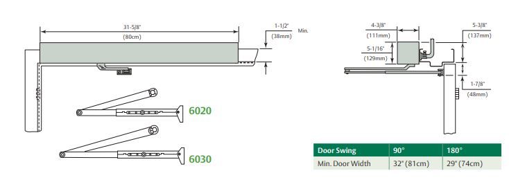
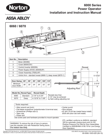
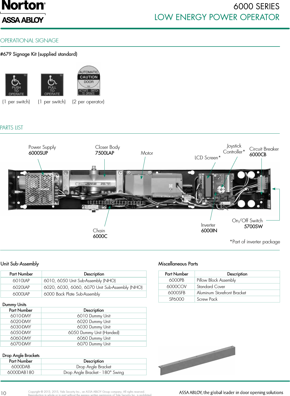
6000 Series. The 6000 Series low energy operator is a heavy-duty unit designed for rigorous, high-use applications. Built-in intelligence enables the operator to safeguard users while providing better door control. Simple installation and adjustment features combined with the unit’s high level of versatility allows for seamless integration ...
ARC 6000 User Guide_v1.31 (630 kb) TASC - 6000, 6300, and 6600 User Guide (544 kb) TASC - 6100 User Guide (644 kb) TASC - 6200 and 6500 User Guide v2.5 (305 kb) TASC - 6200 and 6500 User Guide CE (352 kb) TASC Series Roadside Supplement (48 kb) TeeJet 814 Manual (65 kb) TeeJet 814FM Manual (509 kb) TeeJet 844RA Manual (265 kb)
Nelweld 4000 and 6000 Operations and Service Manual Manual Version 1.19 ... 3.1.2 Recommended Input Wire and Fuse Sizes 23 3.1.3 Physical Dimensions 24 ... trouble-free operation of the Nelweld series of stud welding power supplies. 1.2.1 Safety Advice
Norton 6000 series wiring diagram.
12. Use copper (CU) wire only for all connections. WATERLINE CONTROLS is the optimum choice for any situation requiring the precise control of a water level. It is ideal for automatically maintaining the correct level in cooling towers, storage tanks, or process water applications. WATERLINE CONTROLS Models WLC 3000 through WLC 6000 achieve control
6000-Series Super Tugger ® Cable Pullers Greenlee / A Textron Company 2 D R IL USA KEEP THIS MANUAL Table of Contents Description The Greenlee Super Tugger® cable puller is intended to be used to pull cable through conduit and in tray. The Super Tugger will develop 28.9 kN (6500 lb) of pulling force. See a Greenlee catalog for sheaves, pulling
Nov 17, 2020 · Norton 6000 Series Wiring Diagram Source: img.yumpu.com Read electrical wiring diagrams from bad to positive in addition to redraw the circuit as a straight line. All circuits usually are the same : voltage, ground, individual component, and changes.
Rod Style - 952A, 952D, and 952QD. Manual. Rod Style - 950IS Series Datasheet. Datasheet. Rod Style - 950IS Series Wiring Diagram, 120/240 Volt. Drawing. Rod Style - 950IS Series Wiring Diagram, 24 Volt. Drawing.
the ACS6008 series are connected to two (2) 12V, 7Ah batteries for standby power (Batteries should be connected in parallel). Understand Brivo ACS6000 control panel product compatibility. The ACS6000 control panel is compatible with a large number of standard reader models including the
6000-000: IQT Pro Part-turn Standard - Legacy
Deta Double Switch Wiring Diagram. Walkman wm ex170 cassette player pdf manual download. Pitblado a john wiley sons inc publication lng risk based safety. Deta 6000 Light Switch Wiring Diagram Perfect Hpm Way Light Switch. Wiring Diagram Double Powerpoint With Extra Switch Double Switch. Single Light Switch Wiring Diagram Nz Hpm Delta For A ...
model of VLT 6000 Series being installed. When this occurs, the model can be identified by a "VLT Type 6XXX" number. This number can be found on the red nameplate on the outside left side of the drive enclosure, or the outside right side of a drive with an auxiliary enclosure. A cross reference from the VLT Type to the model number
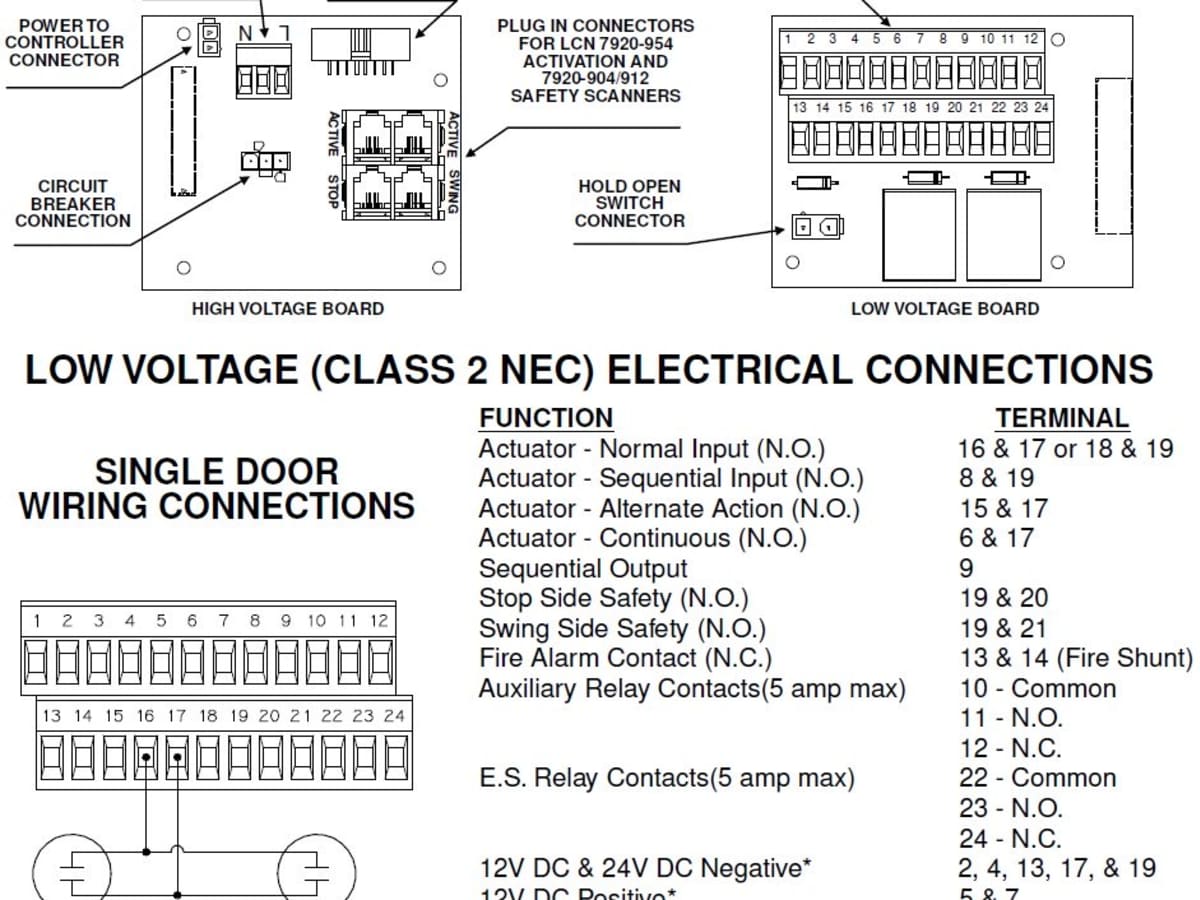
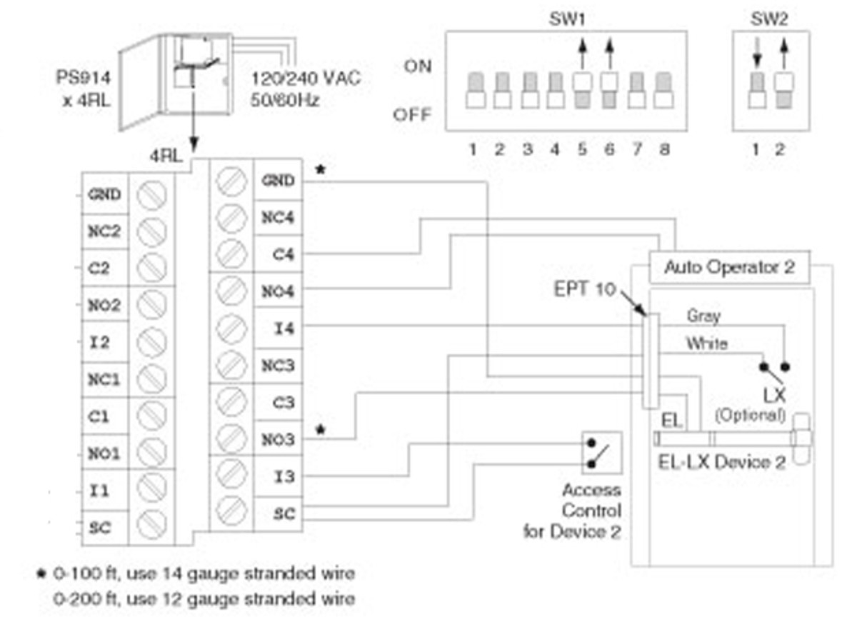
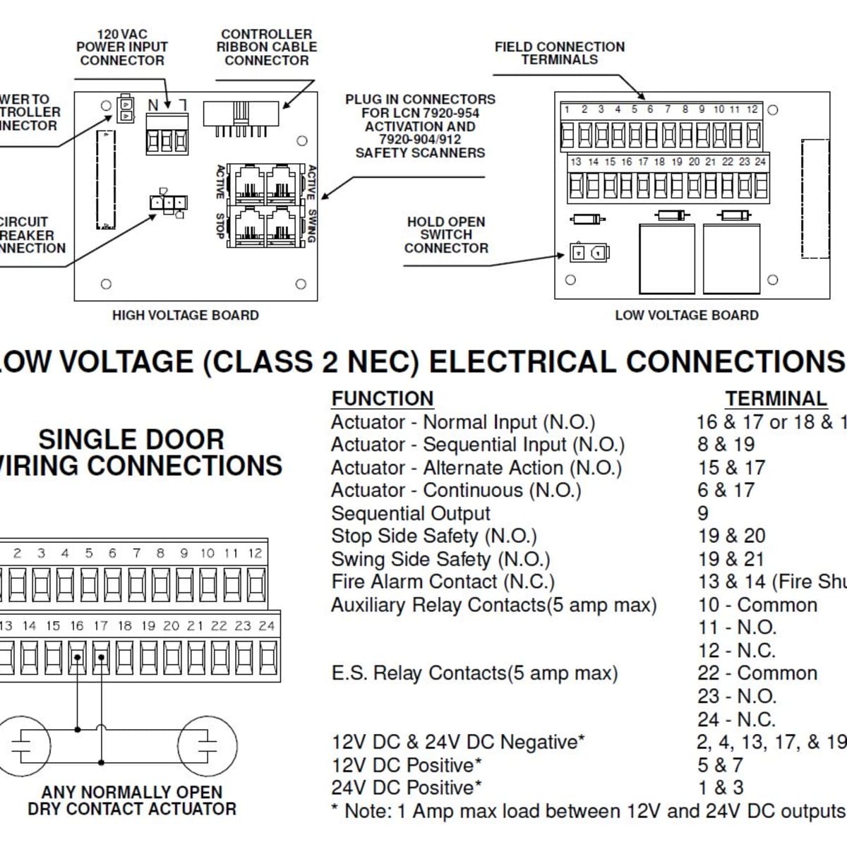
Notes: Permanent wiring is to be employed as required by local codes. Activation devices: push plates, access control, mats, touchless wall switches, etc. Maximum wire size is: 12AWG at terminals LINE and NEUTRAL (120VAC; 60Hz) on Power Input Terminal mounted on inside of end cap. 14AWG at all other terminals. 120VAC, 60Hz.9 amps 24 V DC, max ...
Eaton 9135 Two-in-One UPS 5000/6000 VA User's Guide. English. 14-Oct-2011 6448 kB. Eaton 9135 PPDM. English. 28-Jun-2010 ... Powerware 9315 Series 685 & 1085 Battery Cabinet Installation Manual. English (US) 18-Feb-2003 ... Eaton 93PM Emergency Lighting UPS (150 kW, 480V Three and Four Wire - UL 924) Installation and Operation Manual. English ...
6000-Series HRBs. 6000-Series Hydraulic Release Bearing (98-1110) 8XXX-Series HRBs. 80XX Hydraulic Release Bearing (98-1137) ... Drive-by-Wire for Underfoot Pedal Assemblies (98-1216) Drive-by-Wire for Floor-mount and Hanging Throttle Pedal Assemblies (98-1217)
deta 6000 series cat6 wiring diagram deta cat6 wiring diagram. Reactions. You may like these posts. Popular Posts House Wiring Quotation Pdf. 3:06 AM. Wiring Diagram For Pioneer. 12:36 AM. Exhaust Fan Wiring Diagram With Capacitor. 3:14 AM. Recent Posts 3/recent/post-list Tags
Norton automatic door opener won't work
SERIES 6000 is a 1/16 DIN size panel mount controller. SERIES 4000 is a 1/4 DIN size panel mount controller. SERIES 8000 is a 1/8 DIN size panel mount controller. These units are powered by 11-26VAC/VDC or 90-250 VAC supply, incorporating a 2 amp. control relay output as standard. The second output can be used as cooling control, or an alarm.
.jpg?__aaQuery=aaquery||(direct)||(none)||(not%20set)||(not%20set)||(not%20set)||(not%20set)||(not%20set)||(not%20set)||(not%20set))
6000 series
BREAKBREAKSAFE SAFESAFE SERIES 6000 AND 6000XPSERIES 6000 AND 6000XPSERIES 6000 AND 6000XP ... RED WIRE STOP LIGHT FUSE 10 AMP WIRING DIAGRAM BREAKSAFE BREAKSAFE Break-away switch Black. 12 volt auxiliary line. Normally Pin 2 Red. Stop light circuit Normally Pin 6 Both orange wires to

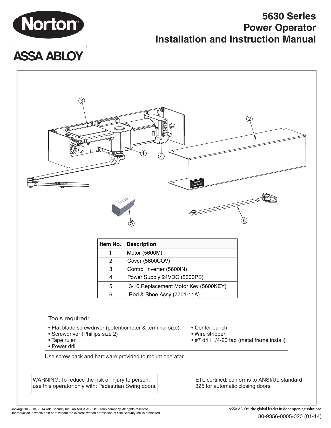
6000 series low energy power operator - pdf free download
Norton 6000 Series Wiring Diagram Effectively read a cabling diagram, one offers to learn how the particular components in the program operate. For instance , if a module is powered up and it also sends out a signal of 50 percent the voltage and the technician would not know this, he'd think he provides an issue, as this individual would expect ...
S e r i e s
Allison Transmission 5000, 6000, 8000, 9000 SeriesOff-Highway Transmissions Commercial Electronic Controls 2 (CEC2) TS3353EN Troubleshooting Manual PDF.pdf. 12.4Mb. Download. Allison Transmission DDEC IV Application and Installation Manual PDf.pdf. 3.2Mb.
S e r i e s
Volume 1 System Architecture and Installation 50-0000-0001/Rev B ® Page 5 of 113 Figure 86. Wiring to a BrooksTM Compact Prover.....88 Figure 87. Controlling the Plenum Pressure of a BrooksTM Compact Prover.....89 Figure 88.
6900 powermatic ® low energy power operator wiring ...
120895 5900 x 24VDC Fail Safe Strike. 120896 5900 x 24VDC Fail Secure Strike. 120897 5900 x 12VDC Fail Safe Strike. 120898 5900 x 12VDC Fail Secure Strike. 120899 5900 x RF. 120900 5900 x 24VDC Mag Lock. 120901 5900 x 12VDC Mag Lock. 120902 5900 x Corbin Russwin M97 M92 to shunt Wall Plates. 120903 5900 x Yale G and B to shunt Wall Plates

Norton 6331-689 6300 series low energy slim profile operator ...
Try to locate that diagram or use this 6000 Series Wiring Diagram to determine which fuse is needed. Reply ? Asked on 12/13/2017 by LARRY HARRIS. are the 6004 and 6600-as the same if not whats the differance thanks Reply A Answered on 12/15/2017 by InyoPools ...
6000 series 6010lap / 6020lap replacement installation and ...
Norton 6000 Series Wiring Diagram Source: img.yumpu.com Before reading the schematic, get common and understand all the symbols. Read the schematic like a roadmap.
6000 series
® TH6000 Series 5 69-1920EFS—01 ENGLISH MCR29453 Wiring Wiring guide — heat pump systems Shaded areas below apply only to TH6320U/TH6220D or as otherwise noted. Thermostat mounting Align the 4 tabs on the wallplate with slots on the back of the thermostat, then push gently until the thermostat snaps in place. Push excess wire back into
Norton 6000 low energy door operator | electrohydraulic ...
Wiring Lights in Series Connection Diagram – Current And Voltage In Series Circuit. First I want to show how to wire lights in series connection, in simple words a series circuit is a circuit in which we have only one path for current flow and only one way to flow the electron. When we talking about the AC or DC light bulbs, we know that we ...
Assa abloy | manualzz
34 Wiring Pictorials 42 600 Series Parts List 57 6000/6100 Series Parts List 67 Ice Maker Parts List 1. General Information and Specification OPERATING LIMITS - ALL MODELS AC Mode: 132 VAC Max., 108 VAC Min. 15.4 VDC Max., 10.5 VDC Min. DC Mode: 15.4 VDC Max., 11.5
S e r i e s
6000 SERIES low EnERgy powER opERatoR • Ease of installation and setup – Simple instructions – Lcd screen and joystick controller • Application versatility and ease of adjustment – non-handed units – Push- or pull-side mounting – interfaces with electric hardware – integrates with access control systems

6000 series low energy power operator - pdf free download
6000/8000 C Series IFT Canadian French. 6000/8000 C IFT Series. 6000/8000 CL IFT Series. 6000/8000 CLX IFT Series. 6000/8000C Modern IFT Series. IntelliFire app User Guide. IntelliFire app Quick Start Guide. IntelliFire Touch IFT-RC150. AIR TIGHT Gas Insert UL Listing: Install Manual ...
Assa abloy
Operator Manuals. Working safely is at the top of your list, so if your operator manual is lost or missing, click on the lift truck model to view its current manual. You can also order manuals using the manual and safety label lookup tool.

433mhz rf1 kit list no. 687 | manualzz
'brown wire' controls (in parallel). In this environment, multiple PT-6000 units will need to be connected to a single, externally switched/controlled, 120V hot circuit. Both 12VAC output channels of each PT-6000 will be controlled by the 120V input power. The PT-6000 input will be connected to externally switched/controlled 120VAC line
6000 series
Note: Details regarding connection of Allen-Bradley Series 6000 photoelectric sensors to Allen-Bradley Programmable Controllers can be found in Publication 42SR-4.0. All wire colors shown refer to Allen-Bradley quick-disconnect cables. Supplied Accessories Mounting Kit #129--106--1 contains 2 plastic nuts, anti-vibration mount, and slip pads.

6000 series low energy power operator - pdf free download
SECTION 5 - ELECTRICAL Description Rev. # Pg. # Pivot Panel - 2-76 to 3-79 .....4-91 5-1

Norton commando wiring diagram - grant tiller
Norton 6000 series installation and instruction manual | manualzz
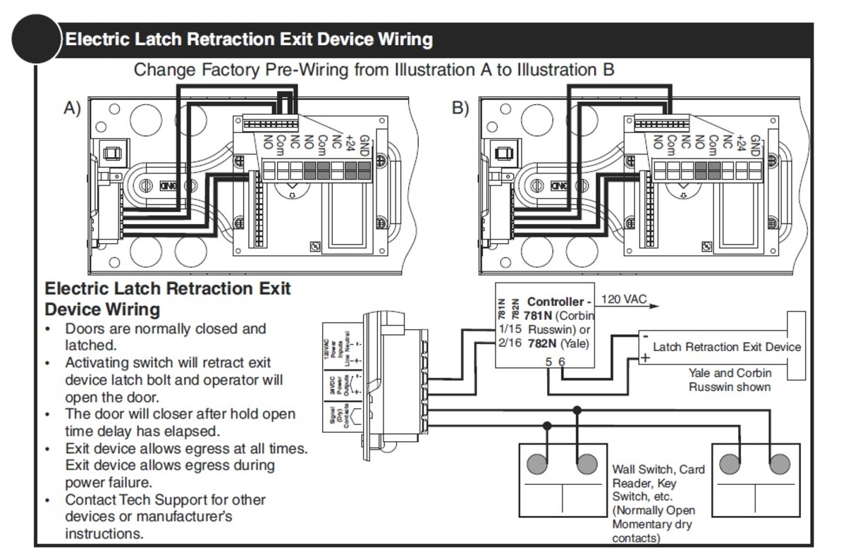
How to coordinate automatic doors with locking devices ...
Assa abloy
||(none)||(not%20set)||(not%20set)||(not%20set)||(not%20set)||(not%20set)||(not%20set)||(not%20set))
6000 series
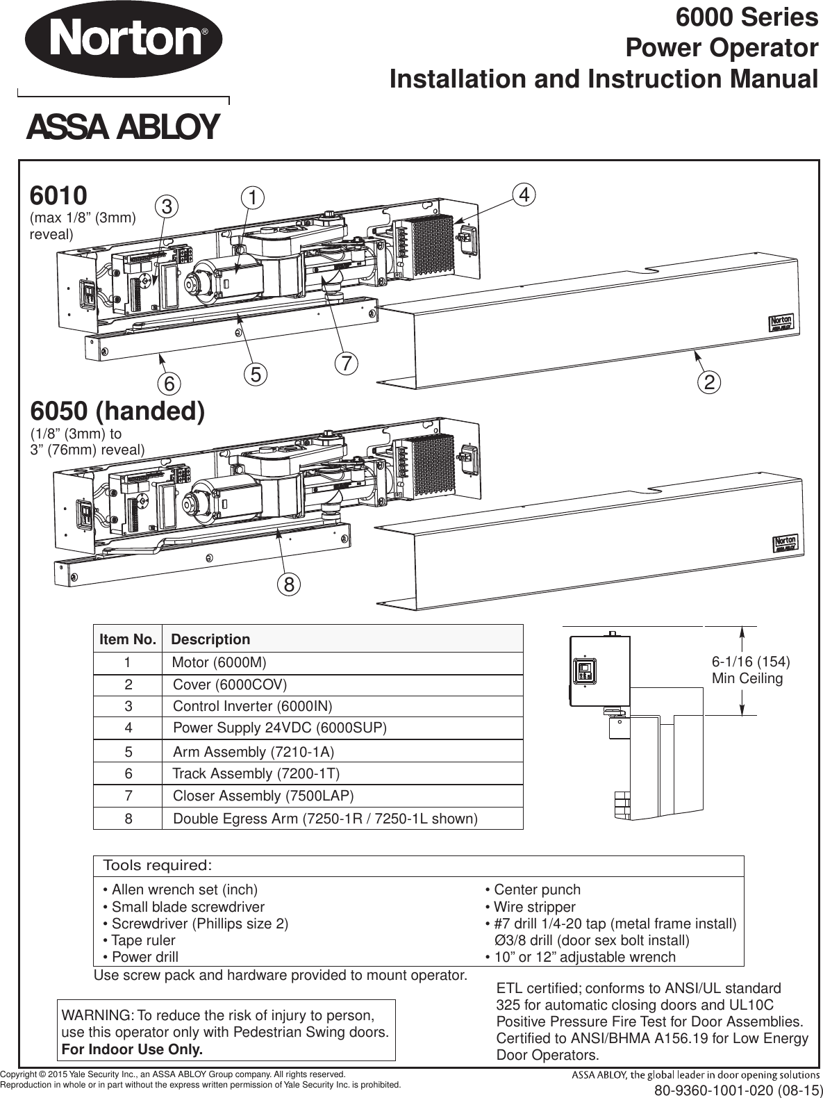
Norton 80 9360 1001 020 6010, 6050 pull side mounting
.jpg?__aaQuery=aaquery||(direct)||(none)||(not%20set)||(not%20set)||(not%20set)||(not%20set)||(not%20set)||(not%20set)||(not%20set))
6000 series
How to coordinate automatic doors with locking devices ...

6000 series low energy power operator - pdf free download

Commando wiring diagram + boyer + podtronics

Norton dominator 99 1960 - mobil & motor terbaru berita ...

6000 series
.png?__aaQuery=aaquery||(direct)||(none)||(not%20set)||(not%20set)||(not%20set)||(not%20set)||(not%20set)||(not%20set)||(not%20set))
6000 series

The electrical wiring diagrams for ramps 1.4 (reference from ...
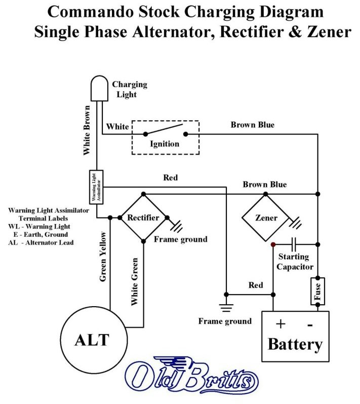
Old britts, simplified wiring diagrams
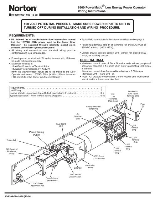
6900 powermatic ® low energy power operator wiring ...

Norton 6000 low energy operator installation video.mov - youtube
Norton 6000 low energy operator 43221 catalog

Wipac wiring diagram - norton "electra" 400cc twin | ebay
How to coordinate automatic doors with locking devices ...
How to coordinate automatic doors with locking devices ...

Details about deta double outlet powerpoint+extra switch 240v 10a, ip54 6000 series-aust brand

Norton 6000 series electrohydraulic low energy power operator
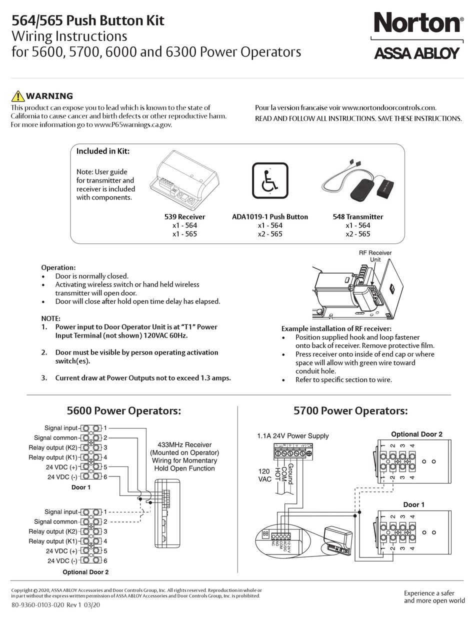
Assa abloy norton 564 wiring instructions pdf download ...
0 Response to "42 norton 6000 series wiring diagram"
Post a Comment