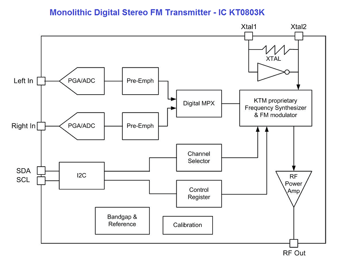
38 fm transmitter block diagram
Block diagram of an FM (frequency modulated) transmitter is given on Pic.2.4. Information being transferred, i.e. the modulating signal, is a signal from some LF source. it is being amplified in LF amplifier and then led into the HF oscillator, where the carrier signal is being created. Radio Transmitter Block Diagram Radio Transmitter Block Diagram This block diagram of a radio transmitter in a communication system is very simple and basic. It is generalised for AM and FM types of modulation, and consists of four subsystems. Communication is the transfer of meaningful information from one location to another.
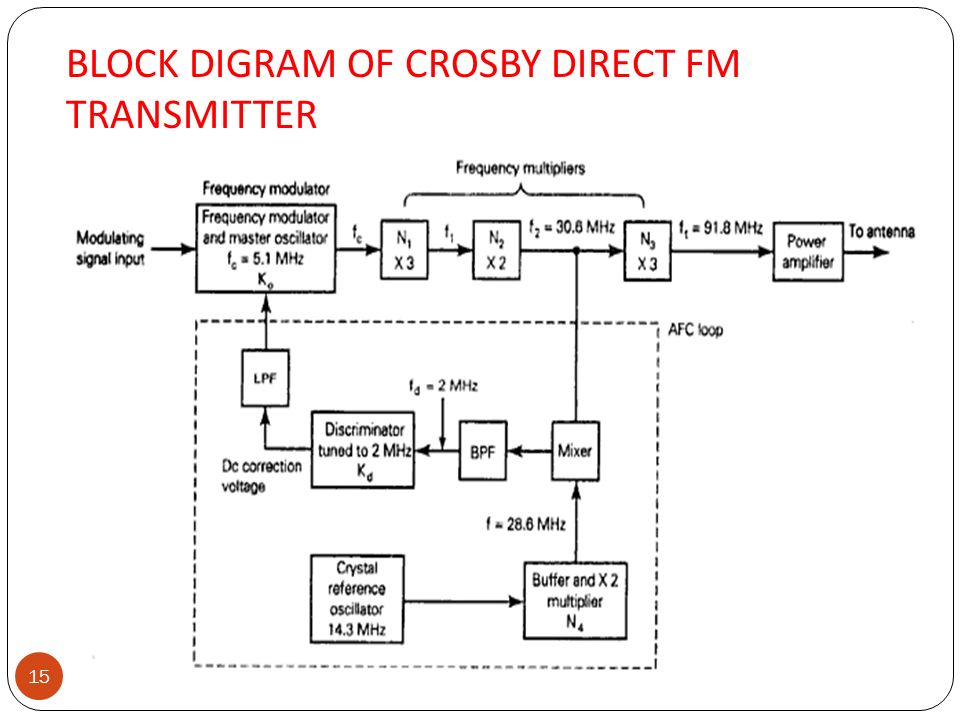
Fig. 4 Hybrid block diagram of a composite FM transmitter. The frequency of Yl is multiplied by a factor of eight as the various doubler stages amplify the signal. Similarly, the deviation at Yl is increased by a factor of eight during the multiplication process Class-C stages are used throughout the transmittar RF section.

Fm transmitter block diagram
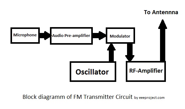
Block Diagram of FM Transmitter Working of FM Transmitter Circuit. The following circuit diagram shows the FM transmitter circuit and the required electrical and electronic components for this circuit is the power supply of 9V, resistor, capacitor, trimmer capacitor, inductor, mic, transmitter, and antenna. Let us consider the microphone to understand the sound signals and inside the mic, there is a presence of the capacitive sensor. Block Diagram for FM transmitter circuit Components required for FM transmitter circuit are modulator, oscillator, RF-Amplifier, Audio pre-amplifier, microphone and antenna. The Diagram shows the Block diagram for FM transmitter circuit. There are two types of frequency in the signal : Carrier signal (with carrier frequency) FM Transmitter Circuit Principle: FM transmission is done by the process of audio pre amplification, modulation and then transmission. Here we have adapted the same formula by first amplifying the audio signal, generating a carrier signal using an oscillating and then modulating the carrier signal with the amplified audio signal.
Fm transmitter block diagram. FM Transmitter FM Modulation using VCO Block Diagram Chipset 4046 PLL 4046 VCO Characteristic Schematic PCB Layout Considerations PCB Layout Measured Results FM Receiver FM Demodulation using PLL Loop Filter Design VCO Design Block Diagram Chipset 4046 PLL Schematic PCB Layout Superheterodyne FM Receiver Block Diagram Chipset TDA7000 IF Filter Quadrature Demodulator IF Harmonic Distortion IF ... F.M. Transmitter Tutorial - Block Diagrams - Electronics Circuit and Tutorials - Hobby Science Projects - The microphone converts sound pressure wave to electrical signals. These audio voltages are amplified by the audio amplifier. The amplified audio is used to control the deviation of the frequency controlled oscillator. FM Broadcast Transmitter Note: Pre-driver, Driver & Final PA Stage each contain important Passive Components Hybrid Matching Capacitors, Inductors, Balun Transformers, & 50 Ohm Terminations Represents Pallet Solution Driver Pre-Driver 50 Ohm Terminations Lightning Protectors (EMPs) Heat-sink, Clamp-compression, etc. Thermal Management Systems A block diagram representing various stages of a basic continuous wave radio transmitter. Following the action in Figure 6, the oscillator creates an ac sine wave at the desired frequency. This signal is called the carrier wave. The carrier wave is then amplified by the radio frequency (RF) power amplifier to the desired output wattage.
Understand the block diagram of an FM transmitter employing either frequency multipliers or mixers to generate the final frequency. Fig. 2 Note A In the diagram the Microphone feed the Audio Amplifier which when feeding the Oscillator directly is feeding it with Frequency Modulation caused by the Microphone. FM Transmitter Working Principle. The main function of an FM Transmitter Circuit is to transmit the sound using radio waves. So, at first, an FM Transmitter Circuit converts the sound or audio into radio wave then it transmit. You can see, in the block diagram of the FM Transmitter, the first block is the Microphone. The block diagram of NBFM modulator is shown in the following figure. Here, the integrator is used to integrate the modulating signal m ( t). The carrier signal A c cos. . ( 2 π f c t) is the phase shifted by − 90 0 to get A c sin. . ( 2 π f c t) with the help of − 90 0 phase shifter. The product modulator has two inputs ∫ m ( t ... May 13, 2021 · Block diagram of a low level FM broadcast transmitter is shown in figure. The master oscillator generates the RF signal (carrier) required for modulation. Master oscillator is generally a well defined LC oscillator. The buffer amplifier is used to make the oscillator frequency free from the loading of the next stages.
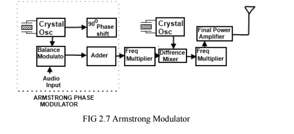
Armstrong FM Transmitter Block Diagram. The crystal-controlled carrier oscillator signal is directed to two circuits in parallel. This signal (usually a sine wave) is established as the reference past carrier signal and is assigned a value 0°. The circuit can also be used as a remote control transmitter. FM Demodulator using PLL - This is a good circuit of an FM demodulator with a schematic diagram, a design of FM demodulator, and working of PLL with block diagram. This will definitely be useful for your educational purposes. FM stereo demodulator using AN7415 - Stereo ... 4a.1 Recall and understand the block diagrams of CW, AM, SSB and FM transmitters. Students are not being able to recall these simple block diagrams and understand what they are. In the CW Tx the morse key is connected into the "keying stage" indicating that the RF oscillator remains undisturbed whilst the keying is carried out. The block diagram of an FDM receiver is shown in fig3. The block diagram of FM transmitter is shown in the following figure. Each signal that needs to be sent over a communication channel undergoes modulation with various carrier frequencies as shown clearly in the diagram below. Fm Transmitter Block Diagram And Explanation Of Each Block Pdf.
88 108 MHz FM Transmitter Circuit
FM Receiver Working Principle. To easily understand the working principle of FM Receiver, see the block diagram. The first block is the Antenna. The antenna is used to receive the radio signals and intercepted it. The next block is Radio Frequency Amplifier or RF amplifier. The RF amplifier is used to amplify the RF signal received by the antenna.

Long range fm transmitter circuit,2 km 88-108 MHz VHF
14 Apr 2015 — Block diagram of FM transmitter and receiver and its explanation · Frequency Modulation is the process in which the frequency of the carrier ...
Arduino FM Transmitter
FM transmitter FM Transmitter Block Diagram Direct Method Using Reactance modulator direct method The FM transmitter has three basic sections. The exciter section contains the carrier oscillator, reactance modulator and the buffer amplifier. The frequency multiplier section, which features several frequency multipliers.

Low Power FM Transmitter
About Press Copyright Contact us Creators Advertise Developers Terms Privacy Policy & Safety How YouTube works Test new features Press Copyright Contact us Creators ...
FM Transmitter Circuit With 3km Range - EEE PROJECTS
The block diagram of FM transmitter is shown in the following figure. The working of FM transmitter can be explained as follows. The audio signal from the output of the microphone is sent to the pre-amplifier, which boosts the level of the modulating signal.
Communication Protocols Assignments: Block diagram of FM ...
Block diagram of FM Transmitter The working of FM transmitter — The audio signal from the output of the microphone is sent to the pre-amplifier, which boosts the level of the modulating signal. This signal is then passed to high pass filter, which acts as a pre-emphasis network to filter out the noise and improve the signal to noise ratio.
Simple One Transistor FM Transmitter Circuit Diagram ...
Fig. 8 illustrates, in block-diagram form, the absolute basics of an SSB transmitter. The carrier is removed at the balanced modulator (balanced out, so to speak), which provides double-sideband, suppressed-carrier output to the sideband filter, FLI. Depending on the crystal used (Yl or Y2), the output from FLI will be
FM Transmitter Circuit Working and Its Applications
The Fig1 shows the block diagram of wideband FM generation through Armstrong method. Fig1. Armstrong frequency modulation system. The source of carrier for the Armstrong transmitter is the crystal oscillator. A relatively low frequency sub-carrier ( f c) is phase shifted by 90° and is fed to a balanced modulator, where it is mixed with the ...

Arduino FM Transmitter - Engineering Projects
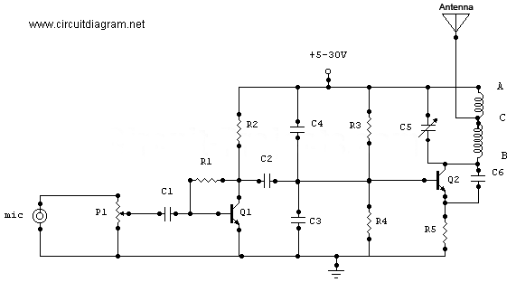
February 07, 2017 Block diagram of FM transmitter and receiver and its explanation FM transmitter Frequency Modulation is the process in which the frequency of the carrier signal is varied by the modulating signal while the amplitude remains constant Using Reactance modulator direct method The FM transmitter has three basic sections.

4 Stage FM transmitter circuit diagram | Circuit diagram ...
A FM transmitter is a device that uses the principles of frequency modulation to broadcast sound supplied at its input. Typical FM transmitter design's usually follow the block diagram below; The signal strength of audio inputs into the transmitter is usually low therefore an amplifier is usually built to bring the signal level up.
FM Transmitter Circuit With 3km Range - EEE PROJECTS
Aug 24, 2021 · Block diagram of an FM frequency modulated transmitter is given on Pic24. Pasternacks library RF and microwave block diagram are designed to provide engineers and designers with examples of common RF systems schematics while illustrating the RF products and where they fit into the systems design.

TX-1000 FM Transmitter Block Diagram Jungsoft
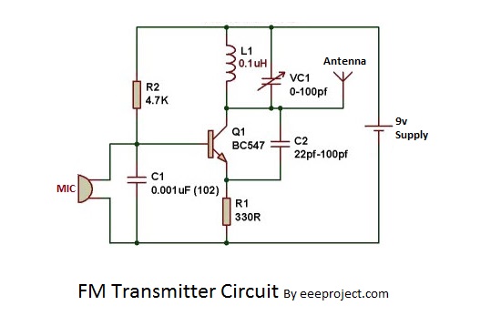
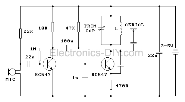
A FM transmitter can cover. Block Diagram of FM Transmitter Working of FM Transmitter Circuit. L1 3 to 4 turns of 22SWG super enamel copper wire 5 to 7 mm diameter air corePlease refer the scanned image of the prototype for getting an idea regarding the coil.
FM Transmitter Circuit
FM Transmitter Circuit Principle: FM transmission is done by the process of audio pre amplification, modulation and then transmission. Here we have adapted the same formula by first amplifying the audio signal, generating a carrier signal using an oscillating and then modulating the carrier signal with the amplified audio signal.

Block diagram of digital FM modulator. | Download Scientific ...
Block Diagram for FM transmitter circuit Components required for FM transmitter circuit are modulator, oscillator, RF-Amplifier, Audio pre-amplifier, microphone and antenna. The Diagram shows the Block diagram for FM transmitter circuit. There are two types of frequency in the signal : Carrier signal (with carrier frequency)
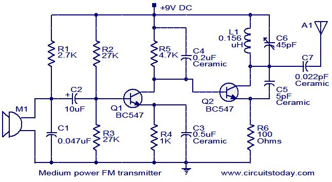
Medium power FM transmitter circuit
Block Diagram of FM Transmitter Working of FM Transmitter Circuit. The following circuit diagram shows the FM transmitter circuit and the required electrical and electronic components for this circuit is the power supply of 9V, resistor, capacitor, trimmer capacitor, inductor, mic, transmitter, and antenna. Let us consider the microphone to understand the sound signals and inside the mic, there is a presence of the capacitive sensor.
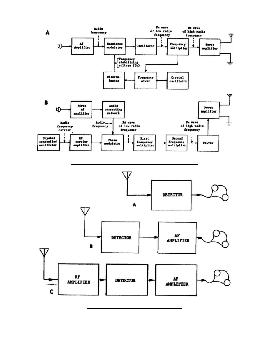
Figure 2-14. Block diagrams of FM transmitters.

FM Modulation System - FM Transmitter, Reactance mod ...
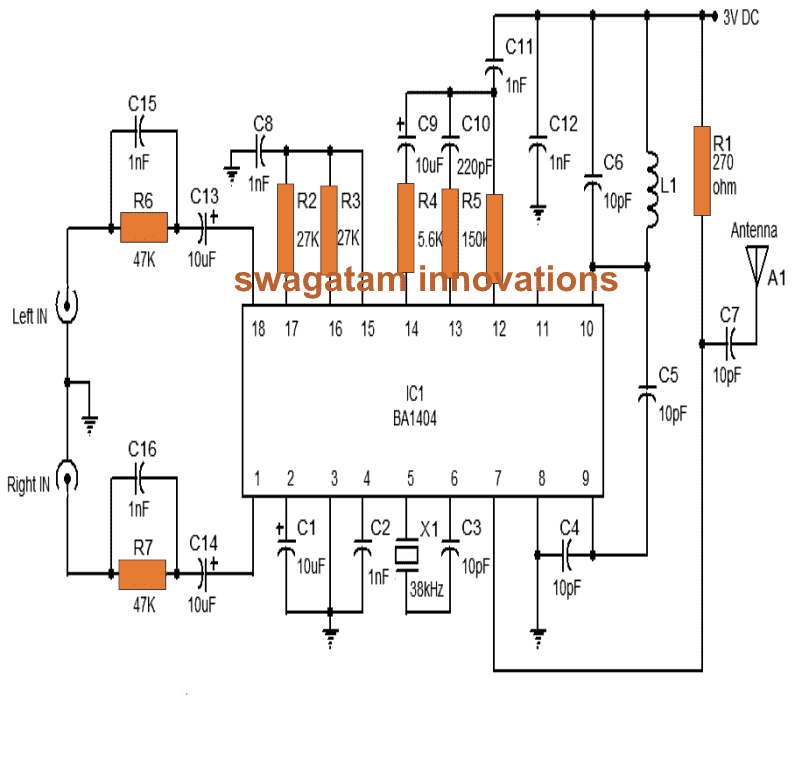
Stereo FM Transmitter Circuit using IC BA1404 - Homemade ...
Block diagram of FM transmitter | Download Scientific Diagram
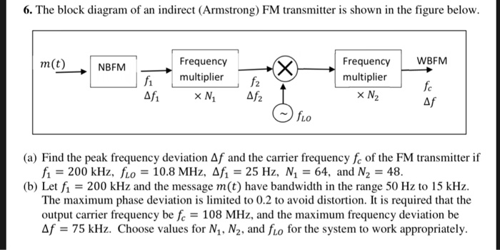
Solved 6. The block diagram of an indirect (Armstrong) FM ...
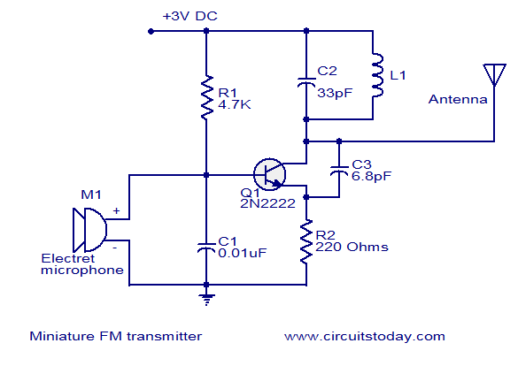
Miniature FM transmitter
Simple FM Transmitter Circuit Diagram and Making It on Breadboard

Transmitter vs Receiver | Transmitter types,Receiver types ...
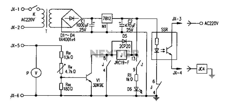
FM transmitter circuit diagram overvoltage protection under ...
FM Transmitter

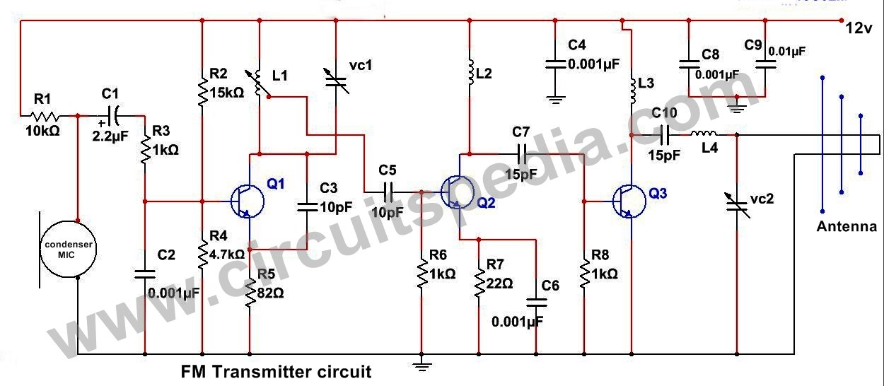
Three Stage 9V FM Transmitter | Electronic Schematic Diagram

High Power FM Transmitter Project - DIY
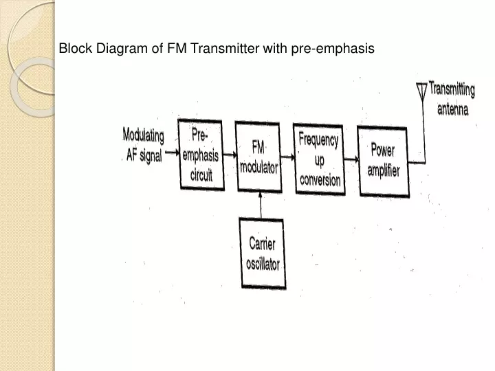
PPT - Block Diagram of FM Transmitter with pre-emphasis ...
5 KM FM Transmitter Circuit Diagram | Long Range FM ...
FM GENERATION Direct Method: when the frequency of carrier is ...

FM Modulation System | Communication system, Fm transmitters ...

FM Transmitter Block Diagram, Working Principle Understand ...

usb fm transmitter circuit diagram
FM Transmitter
1.5 Watt FM Transmitter | Electronic Schematic Diagram

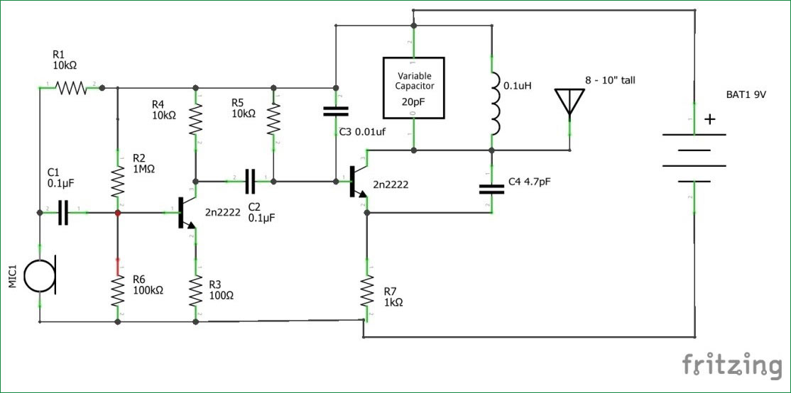
How to Make a 2 Mile, Long Range FM Transmitter Part 1 : 4 ...

Generation Of Fm Block Diagram - Circuit Design

FM Transmitter Block Diagram with Explanation - Electronics ...
0 Response to "38 fm transmitter block diagram"
Post a Comment