38 wiring diagram for air compressor motor
Diagram and Parts List for Porter-Cable Compressor c type-0 Parts - PSI 4 Gallon Oil-Free Portable Air Compressor.This is a valve plate for your compressor or generator. This part controls the air flow into the pump. When the air is pumped by the piston, it passes through the valve plate and into the compressor tank. air compressor pressure switch wiring diagram - You'll need a comprehensive, skilled, and easy to know Wiring Diagram. With this kind of an illustrative manual, you are going to have the ability to troubleshoot, avoid, and total your tasks without difficulty.
Figure 7 Air Compressor Wiring Diagram. Compressor motor wiring doityourself air to 110v devilbiss pro wire 5hp single phase craftsman up for 240v diagram 220 volt basic control circuits practical machinist largest powering 7 the anyone clued with compressors motors instructions arb twin ckmta12 electric starting capacitor problems fix my older help page campbell hausfeld 6 5 hp 3450 rpm 145t ...

Wiring diagram for air compressor motor
Assortment of air compressor motor starter wiring diagram. A wiring diagram is a simplified standard photographic depiction of an electric circuit. It shows the components of the circuit as simplified shapes, and also the power and signal connections in between the tools. Wiring Diagram For Air Compressor Motor from mastertoolrepair.com. Print the wiring diagram off plus use highlighters to trace the signal. When you make use of your finger or perhaps the actual circuit with your eyes, it is easy to mistrace the circuit. 1 trick that We 2 to printing a similar wiring plan off twice. 3 Phase Air Compressor connection / Wiring has been explained with 3 Phase Air Compressor connection Related Videos You Must Watch it will Help :3 Phase Dis...
Wiring diagram for air compressor motor. Today, the wiring diagram necessary to support a given repair procedure is included within that article or a link is provided to the appropriate SYSTEM WIRING DIAGRAM article. For example, the wiring diagram for a Ford EEC-IV system may be included in ENGINE PERFORMANCE and WIRING DIAGRAMS articles for Ford Motor Co. The wiring diagram for a cruise control … As stated previous, the lines in a Air Compressor Wiring Diagram signifies wires. At times, the cables will cross. But, it does not imply link between the cables. Injunction of two wires is generally indicated by black dot to the intersection of 2 lines. There will be main lines that are represented by L1, L2, L3, and so on. H979l Century Carrier Hd60fk652 Electric Motor 5 Hp 1725 Rpm 208 230 460v Com. Magnetek Centrury 7 850121 01 Oj 5hp Ac Motor 1760rpm 230 460v 60hz 3ph. Century Air Compressor Motor 5 Hp Capacitor Start Run Nameplate Rpm 3 450 Voltage 230v Ac 1ata9 B813 Grainger. I Am Looking For An Owners Manual A Sanborn Air Compressor Have Having Very Little ... 04.11.2018 · 230 volt single phase compressor wiring diagram; 230 volt single phase wiring diagram; 230v single phase motor starter wiring diagram ; 24 volt trolling motor battery wiring diagram; 240 volt single phase wiring diagram; 240v single phase wiring diagram; 240v single pole circuit breaker wiring diagram; 240v single pole thermostat wiring diagram; 24v 8 pin …
Ingersoll Rand Air Compressor Wiring Diagram Single Phase - wiring diagram is a simplified up to standard pictorial representation of an electrical circuit. It shows the components of the circuit as simplified shapes, and the capacity and signal contacts in the midst of the devices. A wiring diagram usually gives instruction roughly the ... 5hp Air Compressor Motor Wiring Diagram. 120554 00 leeson 5 hp 3450 rpm 145t 230v air compressor motor com how to wire 5hp single phase 220v reset switch pressure electric solenoid valve 2 figure 7 wiring diagram practical machinist largest manufacturing technology forum on the web technical doent compressed systems special duty 115 230 ... E109968- INSERT CUSTOMER WIRING INSTRUCTIONS ... 230VAC Air Compressor Wiring Instructions ... motor name plate states it is rated for 208 volts single.2 pages Precaution: Identify the air compressor circuit, turn it OFF and Tag it with a Note before working with the 220 volt air compressor wiring. Circuit Wiring for a 240 Volt Air Compressor. Circuit Size for an Air Compressor The circuit size will depend on the size of the air compressor and the horsepower rating of the motor.
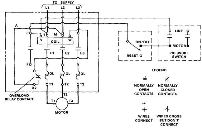
All our compressor motors . Nov 25, · I bought an old air compressor that has a HP electric motor made by GE. It's an old motor, but it works fine. The motor is designed to run on either V or V AC. Sep 12, · I need a wiring diagram. this motor is from a sears 27 gallon horizontal compressor. That's true for Husky 60 gallon air compressor wiring. However, the manufacturer of the Kobalt 60 gallon stationary air compressor recommends 12-gauge wire, even though that machine also runs on 230V power. The difference is due to the fact that the Kobalt machine draws less current. Advertisement Wiring the Switch to the Motor Every air compressor has a pressure switch … Clarke Air Compressor Wiring Diagram. Oleh Gio Mario B Februari 02, 2020 Posting Komentar. Clarke Se16c150 Pump Rebuild Tips Page 4 Mig Welding Forum Clarke Bronco Air Compressor Manual Clarke Champ 265 Specifications Manualzz Com Clarke Se16c150 Pump Rebuild Tips Page 4 Mig Welding Forum Anybody Good With Compressors Motors General Chat Clarke ... Use the wiring diagrams on the back of this sheet to install and connect power wires for the starter and motor. Connect power and ground leads from a fused disconnect or circuit breaker directly to the magnetic starter. Figure 1 is a typical wiring diagram for a three phase magnetic motor starter.
Motor Starter Wiring Diagram Air Compressor - Collection ...
The wiring diagram identifies the fan motor and compressor s wire colors and functions. The basic requirements for wiring electric motors. Identify the air compressor circuit turn it off and tag it with a note before working with the 220 volt air compressor wiring. These tips can be used on most ele. Circuit wiring for a 240 volt air compressor.
Wiring Diagram For Electric Motor For Craftsman Air ...
Refrigeration compressors and air conditioning compressors provide air conditioning, heat pumping, and refrigeration for large-scale facilities and equipment. They use compression to raise the temperature of a low-pressure gas, and also remove vapor from the evaporator. Most refrigeration compressors (refrigerant compressors) are large, mechanical units that form the …
Wiring Diagram For Electric Motor For Craftsman Air ...
07.09.2021 · Idle Air Control Motor - This IAC is a solenoid that bolts to the throttle body and controls idle changes caused by engine loads. When your IAC is going out, you may experience surges or poor idle quality. Thermactor Air Diverter Solenoid - The thermactor air diverter solenoid, commonly referred to as TAD, is a component of your Fox Body's vacuum system. …

Tattoo shop in Gili Air
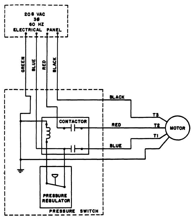
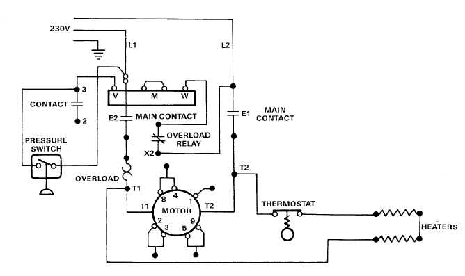
CAMPBELL-HAUSFELD Air Compressor Manual Online: Grounding, Motor Hookup And Starter Installation, Direction Of Use Figure 4 wiring diagram. Campbell Hausfeld Air compressor air pressure switch wiring"/> from the v supply to the switch and 3 wires going from the swith to the motor. In operation a pressure switch turns the power ON and OFF to an ...

Wiring Diagram, Air Compressor Motor Popular Figure 1-7 ...
Wiring Diagram For Air Compressor Motor Ge Com France Nema Motors Manufacturers China Ac Suppliers Factory Common Problems With Air Compressors The Titus Company General electric 5kcr49tn2312cx compressor parts only mara 9f 05 heavy duty gas turbines ge power general electric ge90 wikipedia. Whats people lookup in this blog: ...

Campbell Hausfeld Air Compressor Motor Wiring Diagram
Craftsman Motor Wiring Diagram Wiring Diagram T5 Craftsman Riding Mower Electrical Diagram Wiring Diagram Sears Craftsman 30b0363 Liftmaster Chamberlain Capacitor ... 3 Hp Spl 3450 Rpm U56 Frame 115 230v Air Compressor Motor Craftsman 1hp Capacitor Start Motor Operating Wiring 11312200

Pressure Switch Wiring Diagram Air Compressor - Wiring ...
Vor 2 Tagen · Internal wiring for each junction block is also provided for better understanding of connection within a junction block. Wiring related to each system is indicated in each system circuit by arrows (from_, to_). When overall connections are required, see the Overall Electrical Wiring Diagram at the end of this manual.

Wiring Craftsman compressor up for 240V - DoItYourself.com ...
7.5HP Air Compressor - Motor Starter Retrofit Kit For use with the 45924, 459241, and 459242 Instructions for Installation/Set-up WARNING: SPECIAL HAZARDS ... While assembling, refer to page 23 of this manual for a wiring diagram.

Air compressor wiring - DoItYourself.com Community Forums
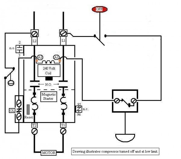
26 Sept 2017 — Air compressor motors are wired directly to an air-operated pressure switch. The pressure switch energizes the electric motor circuit when ...

Capacitor For Compressor Wiring Diagram
Wiring diagram for air compressor motor. Air conditioning circuit and cycle diagram. It has one start and two run capacitors and 3 jumper btw if you have two starts and a run cap, that is not the wiring diagram for your motor. Air compressor symbols of pneumatic system. ...

Compressor motor wiring - DoItYourself.com Community Forums
3 Phase Air Compressor Wiring Diagram - wiring diagram is a simplified welcome pictorial representation of an electrical circuit. It shows the components of the circuit as simplified shapes, and the talent and signal connections amid the devices.
Wiring Diagram For Air Compressor Motor | Wiring Diagram
According to earlier, the lines in a Air Compressor Wiring Diagram 240V represents wires. Sometimes, the cables will cross. However, it does not mean connection between the cables. Injunction of two wires is usually indicated by black dot at the intersection of 2 lines. There'll be principal lines which are represented by L1, L2, L3, and so on.
Unique Wiring Diagram Ac Split Mitsubishi #diagram # ...
3Ø WIRING DIAGRAMS 1Ø WIRING DIAGRAMS Diagram ER9 M 3~ 1 5 9 3 7 11 Low Speed High Speed U1 V1 W1 W2 U2 V2 TK TK Thermal Overloads TWO SPEED STAR/DELTA MOTOR Switch M 3~ 0-10V 20V 415V AC 4-20mA Outp uts Diagram IC2 M 1~ 240V AC 0-10V Outp ut Diagram IC3 M 1~ 0-10V 4-20mA 240V AC Outp uts These diagrams are current at the time of publication ...

Wiring Diagram for Air Compressor Motor | Free Wiring Diagram
I can not get the motor to run with the starter & motor wired for 230v. The starter pulls in and 240v are present at motor. I used the diagram present on the ...
220 Volt Air Compressor Wiring Diagram - Cadician's Blog
22.01.2020 · Wiring Multiple Lights and Switches On One Circuit Diagram– wiring diagram is a simplified tolerable pictorial representation of an electrical circuit.It shows the components of the circuit as simplified shapes, and the aptitude and signal links amongst the devices.

Air Conditioner Capacitor Wiring Diagram - Wiring Forums
Air Compressor Wiring Diagram Schematic - Wiring Diagrams Hubs - Wiring Diagram For Air Compressor Motor. Wiring Diagram arrives with a number of easy to adhere to Wiring Diagram Instructions. It is supposed to assist all of the common consumer in developing a correct program. These directions will probably be easy to comprehend and implement.

Century Condenser Fan Motor Wiring Diagram | Ac condenser ...
The basic requirements for 3 phase air compressor wiring include adding a nameplate for each engine, usually on the side or end of the engine. The label details show the scale of the motor and electric demands. An electrical service then must have either three phase-230 volts or three phase-460 volts for the shop where the motor is to be mounted.

Radio Wiring Diagram | Electrical wiring diagram, Air ...
Ingersoll Rand Air Compressor Wiring Diagram Air Compressor Motor, Electric Compressor, Electrical Circuit Diagram. Visit. Save. From. tankbig.com ...
![[32+] 3 Phase Air Compressor Motor Starter Wiring Diagram](https://blogger.googleusercontent.com/img/proxy/AVvXsEh_68a_GwcPy1v8DO8dvH3AOb1disSnSeeQtPigIk49FdvN5L5XipSfmTzu7DLSKSgFxC-hnpvcW-RzqFhKURGai6IhvIDfAhZoFUP5d0lbpiw1sAOCdXYZJPI_znBZ2Ua_G4Z4kRyx5yczUx4JrzoYmGsaHUxxNFpXL9a5rUFugEfDFF0q6QyWdg5n7EU6kWCs_24CIa8jzVprd8sxhwUL36hUruVjN2U9jz32NMLJ5tJqpSEG81Ceszq-UTepioMZ82s=w1200-h630-p-k-no-nu)
[32+] 3 Phase Air Compressor Motor Starter Wiring Diagram
Thanks for your electrical wiring question Cody. Wiring a 3 Phase Motor for an Air Compressor. The Basic Requirements for Wiring Electric Motors. Every motor should have a name plate which is typically attached on the side or end of the motor. The information found on the label tells all about the motor size and electrical requirements.
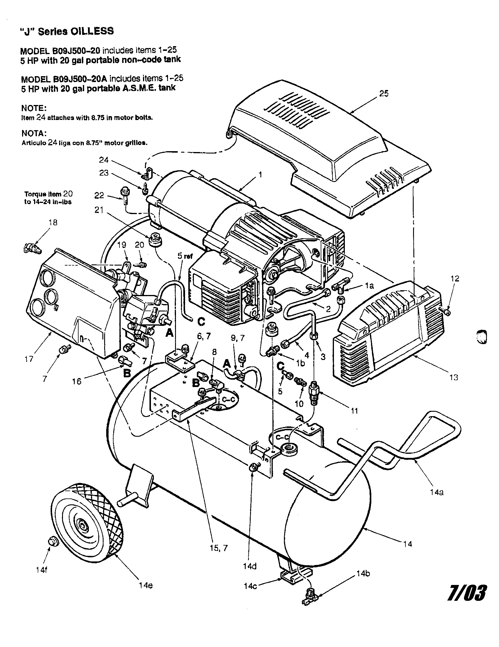
COLEMAN 5 H.P. AIR COMPRESSOR Parts | Model b09jl50020a ...
The problem was that the wiring on the tag of the motor was unreadable and there was no diagram inside the cover. So far I have tried numerous times to get in contact with Emerson, without any success, but got a good technician at Campbell Hausfeld. He has send me pictures on how to change the wiring from 120V to 220V.

Ingersoll Rand Air Compressor Wiring Diagram | Electrical ...
Variety of wiring diagram for air compressor motor. A wiring diagram is a simplified traditional pictorial representation of an electrical circuit. It reveals the parts of the circuit as streamlined shapes, and also the power and signal links between the gadgets.

Century Ac Motor Wiring Diagram 115v 2hp Definite Purpose ...
30.08.2015 · Home Refrigerator & Air Conditioner What is Role of PTC Relay and How a Compressor PTC Relay works . by Sikandar Haidar-10:02:00 AM. 17. In my last post, I talk about the compressor overload, and in this post, you will learn about PTC Relay which we use mostly for every refrigerator compressor starting. PTC means a positive temperature coefficient …

Wiring Diagram For Electric Motor For Craftsman Air ...
Unique Wiring Diagram Ac Split Mitsubishi Refrigeration And Air Conditioning Hvac Air Conditioning Hvac Air. 55 New Potential Relay Wiring Diagram Electrical Circuit Diagram Ac Capacitor Electrical Diagram. Great Single Phase Starter Wiring Diagram A Big Compressor Throughout Air Compressor Pressure Switch Electrical Wiring Diagram Electric ...

Compressor motor wiring - DoItYourself.com Community Forums
3 Phase Air Compressor connection / Wiring has been explained with 3 Phase Air Compressor connection Related Videos You Must Watch it will Help :3 Phase Dis...

Compressor Motor Capacitor
Wiring Diagram For Air Compressor Motor from mastertoolrepair.com. Print the wiring diagram off plus use highlighters to trace the signal. When you make use of your finger or perhaps the actual circuit with your eyes, it is easy to mistrace the circuit. 1 trick that We 2 to printing a similar wiring plan off twice.

1997 HONDA CR-V AIR CONDITIONING CIRCUITS SYSTEM WIRING ...
Assortment of air compressor motor starter wiring diagram. A wiring diagram is a simplified standard photographic depiction of an electric circuit. It shows the components of the circuit as simplified shapes, and also the power and signal connections in between the tools.

I purchased a Baldor L1430T single phase 5 HP motor to ...
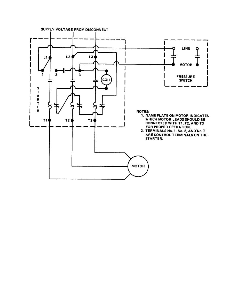
Figure 1-3. Wiring diagram. - TM-5-4310-356-140010

A couple of Papuan Frogmouths which have taken up residence at the Lazy Lizard Motel in Port Douglas, Australia.
Electric Motor Controls Wiring Diagrams (115V) - TM-5-4310 ...

Air Compressor Wiring Diagram 230v 1 Phase | Free Wiring ...

Air Compressor Motor Wiring Schematic - Wiring Diagram
Air Compressor Pressure Switch Diagram

Wiring Diagram For 220 Volt Air Compressor, http ...
Sanborn 60 Gallon Air Compressor Wiring Diagram

RIDGID R0230 Wiring Diagram - Master Tool Repair

Air Compressor Capacitor Wiring Diagram Before you call a ...
On-Board Air Compressor
0 Response to "38 wiring diagram for air compressor motor"
Post a Comment