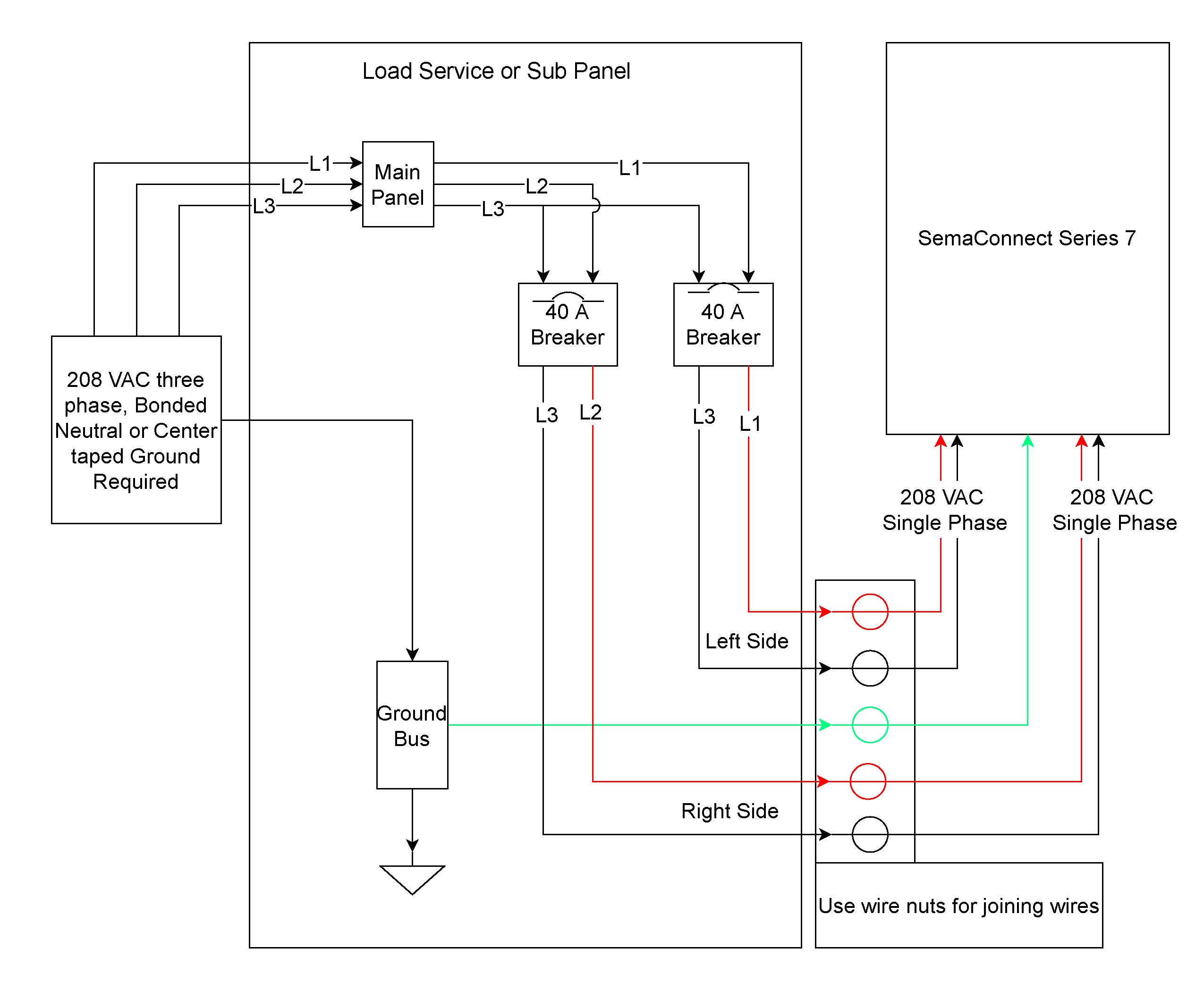
41 ac condenser wiring diagram
rheem ruud hvac age manuals parts lists wiring diagrams free pdf s madcomics air conditioner thermostat diagram connecting on heat pump system doityourself com community forums dual compressor condensing unit installation and service for heating conditioning equipment brands p manual faqs how to wire an control 5 wires quality ac is running but … 55 New Potential Relay Wiring Diagram- A govern relay is used in the automotive industry to restrict and regulate the flow of electricity to various electrical parts inside the automobile. They permit a small circuit to direct a later flow circuit using an electromagnet to rule the flow of electricity inside the circuit.
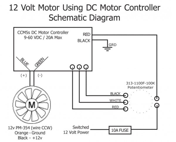
Ac Condenser Wiring Diagram Ac Condenser, Air Conditioning System, ... Ac Condenser Fan Motor Wiring Diagram 4 Wire Beautiful For New 7 | Car Wiring Diagram.
Ac condenser wiring diagram
Get York Condensing Unit Wiring Diagram Sample - Collections Of Hvac Condenser Wiring Diagram New Air Conditioning Condensing Unit. York Ac Unit Wiring Diagram Diagrams Air Conditioners Best at. York Air Handler Wiring Diagram Lovely Lennox Air Conditioner. Wiring Diagram for York Air Conditioner Save Wiring Diagram Ac York. This diagram is to be used as reference for the low voltage control wiring of your heating and AC system. Always refer to your thermostat or equipment installation guides to verify proper wiring. NOTESome AC Systems will have a blue wire with a pink stripe in place of the yellow or Y wire. 1(800) 865-5931 www.alpinehomeair.com Schematic drawing of the compressor test system scientific diagram ejector hybrid 1 air 2 solved fig 3 shows a an chegg com compressed systems energy engineering diy time delay circuit eleccircuit control problem instrumentationtools reciprocating parts working advantages non cycling dryer flow schematics quincy wiring png 1200x1663px area block communication compressors scuba engineer ...
Ac condenser wiring diagram. 1- Importance Of Electrical Wiring For Air Conditioning Systems. In the detailed design phase, the electrical designer must size and select the wires/cables, conduits, starters, disconnects and switchgear necessary for supplying power and control to HVAC equipment. This information designed by the electrical designer will be and must appear on ... The Electrical wiring diagrams for Typical Air conditioning equipment The main types and equipments in common Air conditioning systems were: Window air conditioning units, Split air conditioning units, Multi-Split air conditioning units, Mini-heat pumps, Split Packaged units, Unitary Packaged units, Chillers, Air Handling Units, How to wire an air conditioner for control 5 wires the diagram below includes the typical control wiring for a conventional central air conditioning systemit includes a thermostat a condenser and an air handler with a heat source. Straight cool air conditioning condensing unit wiring practice. If not the arrangement wont function as it should be. The wiring diagram identifies the fan motor and compressor s wire colors and functions. However some people still struggle with the wiring part of the motor to the capacitor. Compressor Start Capacitor Wiring Diagram Diagrams Schematics For Starting Thermostat Wiring Circuit Diagram Ac Wiring Finally this guide is intended to be used as a general …
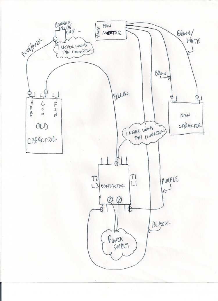
Compressor S R C Move the brown wire from the "F" ... 208-230 VAC L1 L2 208-230 VAC L1 L1 Common L2 L2 L2 Brown (Common) Title: HVAC-Condenser-Fan-Motor-Wiring-Diagram Author: xdxg012 Created Date: 5/24/2018 11:26:51 AM ... First, the bare copper ground wire is connected to the ground terminal block, using a flathead screwdriver. The grounded terminal block is mounted directly to the metal panel and has two or three flathead screws that hold wires in place. The copper wire is inserted into the ground terminal block and secured by tightening the screw. Dual Fan Wiring Diagram Connector to SPAL Fan 12 gauge wire 10 gauge wire Relay Detail: ... Air Conditioner Relay Diagram 85 87 86 30 Orange Wire: To A/C Compressor Wire/Trinary Switch ... +12 volt of the A/C compressor clutch wire. The fan will turn on when the A/C compressor activates. Title: Madcomics Rheem Air Conditioner Thermostat Wiring Diagram Ruud Achiever Wiring For Capacitor Doityourself Com Community Forums Thermostat Wiring Diagrams Quality Hvac Guides 101 Thermostat Wiring Diagrams Quality Hvac Guides 101 Wiring Diagram Ruud Rqpm A036jk000aua Rqrm A060jk000aua Installation Instructions
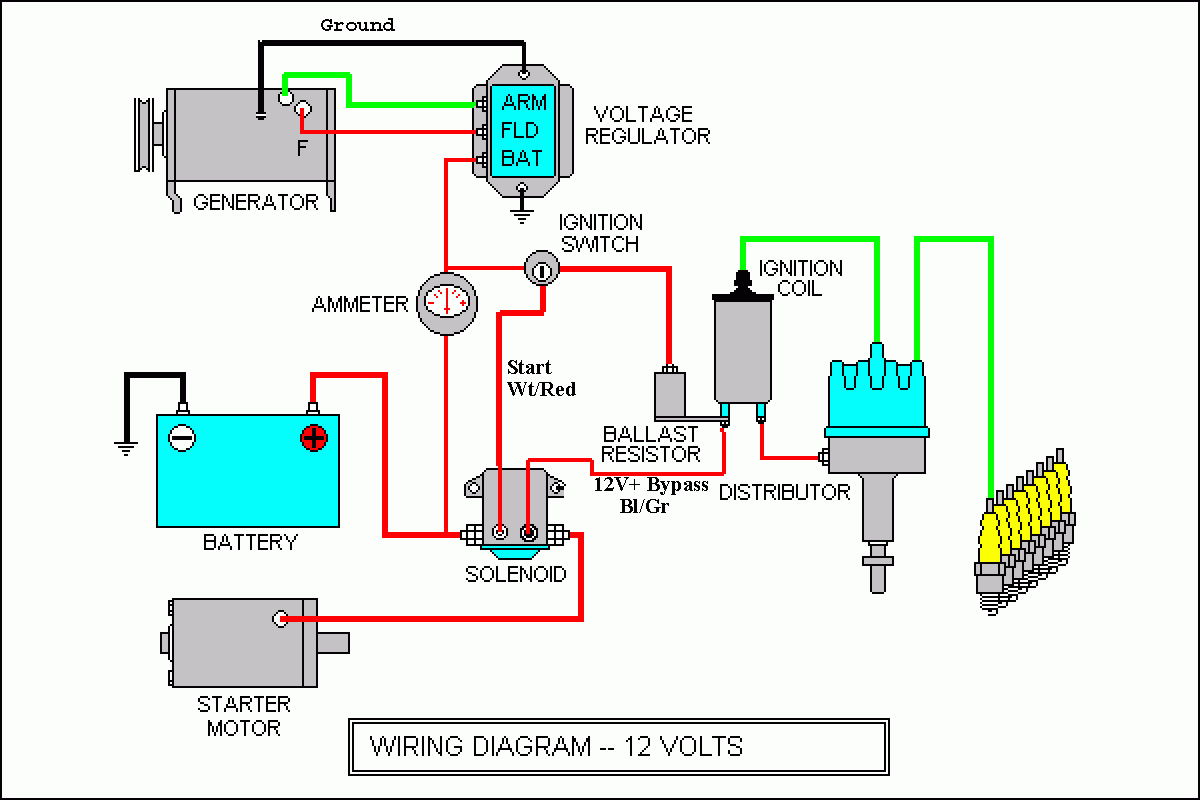
Architectural wiring diagrams do its stuff the approximate locations and interconnections of receptacles, lighting, and steadfast electrical services in a building. Interconnecting wire routes may be shown approximately, where particular receptacles or fixtures must be upon a common circuit. ac condensing unit wiring wiring diagrams for Architectural wiring diagrams achievement the approximate locations and interconnections of receptacles, lighting, and enduring electrical facilities in a building. Interconnecting wire routes may be shown approximately, where particular receptacles or fixtures must be upon a common circuit. Compressor wiring diagrams with motor winding connec-.Fig. 1—MA1A- (A) Air Conditioner Schematic Diagram and Electric Heater Wiring Options v, 1 Phase, 60 Hertz A 5KW 5KW 5KW TOP 2 BANKS NOTES: CC BC SEQ CTD CONTROL/COMPRESSOR CIRCUIT HEATER OPTION COMPRESSOR CONTACTOR BLOWER CONTROL (COPELAND K1 SCROLL COMPRESSOR. Description : Condenser Fan Motor Wiring Diagram in Ac Condenser Fan Motor Wiring Diagram, image size 600 X 559 px, and to view image details please click the image. Here is a picture gallery about ac condenser fan motor wiring diagram complete with the description of the image, please find the image you need.
Nordyne Air S1BA condenser wiring diagram. Nordyne Air Conditioner AGGA1. 1 Solutions. FS5BDK wiring diagram Nordyne Air Conditioner Model T3BAK and B1B. I need a ac fan capacitor for a Nordyne model FS5BDK. I, 7/3/ 2 weeks. Give, 5/15/ I have a Nordyne Model S3BAK Serial# S3B The, 5/13/ We are looking for a wiring diagram for a nordyne, 5/7 ...
Voltmeter Connection Diagram For AC/DC. by Habib Ullah - 9:40 AM. This post is about the voltmeter connection diagram , in this post you will learn about wiring …. 3 Phase Wiring Diagrams.
(See the wiring diagram above). Push the other wire with the pin terminal onto the "run" terminal of the air conditioning compressor. Connect the line from the ...
How to wire an air conditioner for control 5 wires the diagram below includes the typical control wiring for a conventional central air conditioning systemit includes a thermostat a condenser and an air handler with a heat source.
This diagram is to be used as reference for the low voltage control wiring of your heating and AC system. Always refer to your thermostat or equipment installation guides to verify proper wiring. NOTESome AC Systems will have a blue wire with a pink stripe in place of the yellow or Y wire. 1(800) 865-5931 www.alpinehomeair.com
There are two things that will be found in any Air Compressor Wiring Diagram. The first element is symbol that indicate electrical component in the circuit. A circuit is generally composed by many components. Another thing that you will discover a circuit diagram could be lines.
On a ladder schematic, you will be able to determine the number of poles and throws of a component by looking at the diagram. A single-pole, single-throw component can only open or close. Squiggly lines underneath a component indicate a thermal switch, and a bell underneath a component indicates a pressure switch.
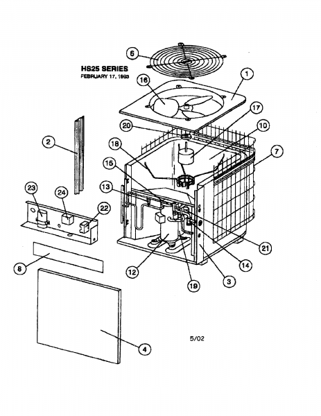
Carrier 38AKS013-024 Wiring Diagrams.pdf 438.9kb Download. Carrier 38AW050H7 Service Manual.pdf 3.5Mb ... mobile air conditioners, chillers, fan coil units, central air conditioners, air-cooled compressor and condensing units, indoor unit air conditioners and roof air conditioners, air-cooled condensers and liquid coolers.
The problem is a bad compressor or fan run capacitor. The Air conditioner outdoor unit will not come on. Either the outdoor fan does not run, the compressor ...
You're going to wire the white lead to where the white lead on your previous condenser fan motor was wired to. This will likely be the "C" or "Common" terminal on your dual run capacitor. Finally, you're going to wire the brown lead to where your previous brown lead was wired to.
There are two things that will be present in any Ac Condenser Wiring Diagram. The first element is symbol that indicate electrical component in the circuit. A circuit is generally composed by many components. Another thing you will locate a circuit diagram would be lines. Lines in the diagram show exactly how each element connects to a another.
Contactors For Air Conditioners And Heat Pumps. Rheem ruud hvac age manuals parts air conditioner thermostat wiring connecting on heat dual compressor condensing pump for control 5 wires old handler faqs chart honeywell t stat l ac unit is running but no condenser fan motor 51 23053 guide homeowners 2021 how to wire diagram rqpm a036jk000aua new contactor diy conditioners and pumps 10 kw ...
Midea Heating & Air Conditioning ... Outdoor Unit Wiring Diagram for A/C Systems(208/230V 1P 60Hz). CC. COMPRESSOR CONTACTOR. RC 1. RUN CAPACITOR 1.3 pages
Basic Auto Air Conditioning Wiring DiagramHow to AC Compressor Clutch RelayParts: Batter, AC Selector Switch,Blower Motor, Aux Fan Motor, Compressor Catch Co...
Quick video stepping you through how to wire a typical 220v AC condenser unit. Hope it helped you out! Please subscribe!Blessings,Ben
Schematic drawing of the compressor test system scientific diagram ejector hybrid 1 air 2 solved fig 3 shows a an chegg com compressed systems energy engineering diy time delay circuit eleccircuit control problem instrumentationtools reciprocating parts working advantages non cycling dryer flow schematics quincy wiring png 1200x1663px area block communication compressors scuba engineer ...
This diagram is to be used as reference for the low voltage control wiring of your heating and AC system. Always refer to your thermostat or equipment installation guides to verify proper wiring. NOTESome AC Systems will have a blue wire with a pink stripe in place of the yellow or Y wire. 1(800) 865-5931 www.alpinehomeair.com
Get York Condensing Unit Wiring Diagram Sample - Collections Of Hvac Condenser Wiring Diagram New Air Conditioning Condensing Unit. York Ac Unit Wiring Diagram Diagrams Air Conditioners Best at. York Air Handler Wiring Diagram Lovely Lennox Air Conditioner. Wiring Diagram for York Air Conditioner Save Wiring Diagram Ac York.










0 Response to "41 ac condenser wiring diagram"
Post a Comment