37 accelerator pedal position sensor wiring diagram
Nov 23, 2021 · Cat Accelerator Pedal Position Sensor Wiring Diagram. November 23, 2021. January 13, 2022. · Cat 5. by tamble. If you are searching for Cat Accelerator Pedal Position Sensor Wiring Diagram, you are at the right site. We provide some wiring diagram for Cat 5. Download the diagram below: A couple weeks ago I got a P2138 code on my 2006 CR-V. The CEL and VSA lights came on, and the car ended up in limp mode but I got home safely. That issue has not happened since (no CEL/VSA lights either). After some reading, it seems the Accelerator Pedal Position Sensor (APPS) is usually the culprit for P2138. I unplugged and re-plugged the wiring harness myself (just in case it was loose/dirty) and got a new battery installed in the meantime. I also brought the car to a local honda dea...
Various obd2 read a throttle body error as p1121 which is an apps malfunction. The 01 4runner sr5 does not have a apps! Its actually the throttle position sensor. Even autozone read it as a p1121 Edit: p1120 is for the TPS
Accelerator pedal position sensor wiring diagram
The car seems to still show some of the symptoms of the bad wiring (fluctuating idle, some smoke sometimes), so now I need to check if my throttle actuator is in good condition, so I am looking for the pin designation on the throttle actuator's plug, or the internal diagram (or schematic) to make electrical tests to see if the throttle position ... Hi need help finding a good App Sensor online for My 2007 Z. Accelerator Pedal Position Sensor Wiring Diagram – wiring diagram is a simplified satisfactory pictorial representation of an electrical circuit. It shows the components of the circuit as simplified shapes, and the skill and signal links amongst the devices.
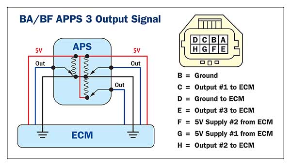
Accelerator pedal position sensor wiring diagram. 2013 Ford Fiesta 1.6l DOHC 150k miles I have been having an intermittent issue where occasionally the wrench will come on and I get the “Engine Malfunction” reading on the radio. When this would happen I would: A: Be in a parking lot and if I pressed the accelerator the engine would not respond. B: If I were on the road it would generally put me on low power mode. I plugged in FORScan and it showed me I had a p2138 Throttle/Pedal Position Sensor/Switch D/E Voltage Correlation. When I turn on l... mounted on the accelerator pedal. The accelerator pedal assembly is serviceable to the extent that the APS/IVS switch can be replaced without replacing the complete assembly. Accelerator Position Sensor (APS) The ECM sends a regulated 5V signal through the ECM black chassis connector terminal 3 to APS connector terminal C. The accelerator pedal position sensor is mounted on the accelerator pedal to detect how much it is de-pressed. It has 2 sensor terminals (VPA and VPA2) to detect the accelerator pedal position and a malfunction ... WIRING DIAGRAM INSPECTION PROCEDURE 1 READ VALUE OF HAND-HELD TESTER(ACCEL POS #1 AND #2) (a) Connect the hand-held tester to ... I bought my '18 Focus in February of '18, new off the lot, and have relished every one of the 34000 miles currently on it. Unlike a lot of owners, I didn't take the Powershift transmission, but went for the EcoBoost 1.0 with a manual. It's been a phenomenal car so far with one exception: It likes to eat the accelerator pedal position sensor about every 10,000 miles. The first one went out at about 9500 miles; the way I knew it was failing was that the engine wouldn't return to idle very well...
Hey Guys, My team just bought a Penny+Giles dual-ouput APPS, the TPS280DP. I know previous FSAE electrical teams have used this sensor, and I was wondering whether this sensor has a dual-sensor alongside a dual output, so that I can just use this one sensor alone for the APPS. The FSAE 2021 rules require that 2 sensors are required for APPS. Here's the datasheet: [/www.cw-industrialgroup.com/getattachment/42e067a7-d2f3-4b9c-962f-8490230a72ff/srh-tps-nrh\_brochure](https://www.cw-industrialgroup... Accelerator pedal position sensor wiring diagram wiring diagram is a simplified satisfactory pictorial representation of an electrical circuit it shows the components of the circuit as simplified shapes and the skill and signal links amongst the devices. We collect plenty of pictures about 2003 Dodge Ram 2500 57 Hemi Throttle Body Wiring Diagram. Accelerator Pedal Released Position Learning is an operation to learn the fully released position of the accel- erator pedal by monitoring the accelerator pedal position sensor output signal. It must be performed each time harness connector of accelerator pedal position sensor or ECM is disconnected. Hello, I am a college student running a self-made car club. Can you explain how the ready-to-drive sound is connected to the Accelerator Pedal Position Sensor? The method I am trying to do is to use a pressure sensor to make a sound when pressure is sensed. I don't know how to get this to work, does anyone know?
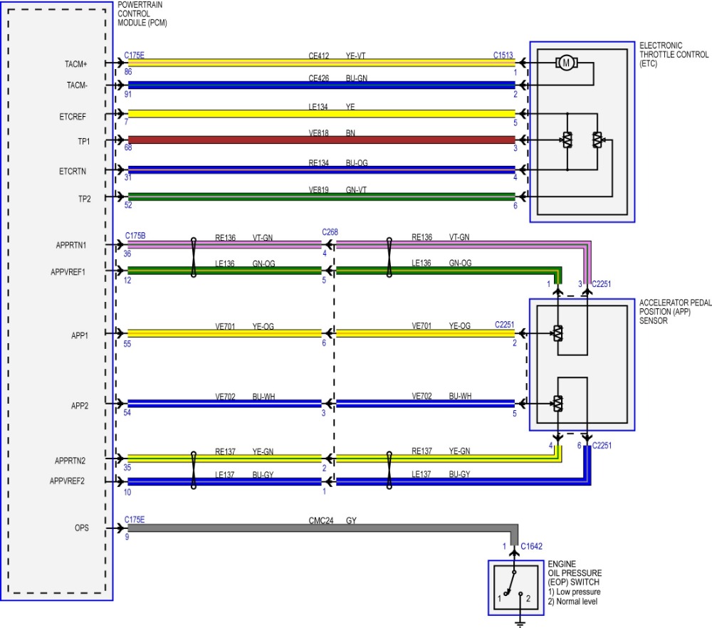
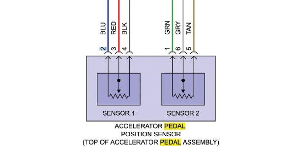
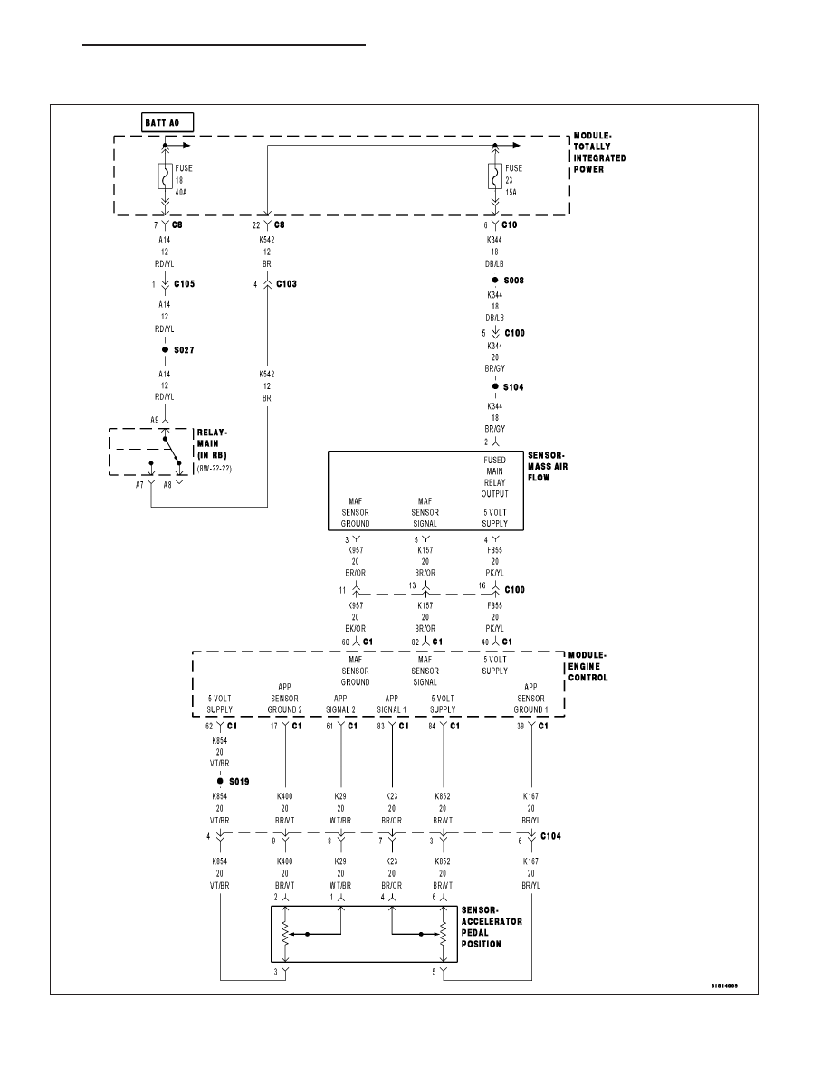
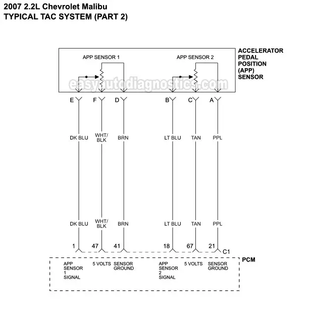
Ford F-Series V10 6.8L Engine Sensor Location Guide. Oct 8, 2020 erwincsalarda. Ford F-Series V10 6.8L Engine Sensor Location Guide Accelerator Pedal Position Sensor Air Flow Meter/Sensor Air Temperature Sensor Ambient /…. Ford Car Sensors and Wiring Diagram Sensors and Wiring Diagram. Table Accelerator Pedal Sensor Wire Colors and Signals.Feb 16, · throttle loss Discussion in 'International Forum' started by sul, Feb 10, Feb 10 There is something wrong with the pedal sensor or related wiring. Throttle position sensor faults cause the engine to idle only and set a "Stop" engine light. Yesterday (on my way home from getting my cats replaced) my car just stopped getting any power whatsoever when I pushed the gas. I am going to replace the app sensor, I watched videos on YouTube, it seems simple enough. But I am wondering about reprogramming it? A few things I read mentioned that and I am unsure how to go about that part. Any tips would be appreciated. It’s a 2011 Nissan Versa. In this example, the Accelerator Pedal Position (APP) sensor is of the potentiometer type. It receives two reference voltages from the Powertrain Control Module (PCM), having two ground wires and two signal wires that send a varying voltage back to the PCM relating to accelerator pedal position. The signal voltage sent back to the PCM may vary ...
I just recently had the app sensor replaced on my ‘07 ridgeline and not sure that it was calibrated afterwards as the check engine light has come back on after a short time off. can anyone give me a heads up on whether this is something I can do on my own or should I take it back to the mechanic? I’m pretty handy at these things and am an electrician by trade. any tips would be greatly appreciated
accelerator pedal position sensor wiring diagram - You will need a comprehensive, skilled, and easy to understand Wiring Diagram. With such an illustrative guidebook, you'll be able to troubleshoot, prevent, and full your assignments with ease.
That the Accelerator Pedal Assembly is made up of 3 individual position sensors. Each one has separate signal, Ground, and 5.0 volt reference circuits. That APP Sensor 1's signal increases as the accelerator pedal is depressed, from below 1.1 volt at 0% pedal travel (pedal at rest) to above 2.1 Volts at 100% pedal travel (pedal fully depressed).
I’ve got a 2001 LS430 that I’ve owned for almost 2 years. Every time the temp get above 85° I experience an intermittent loss of power as I drive. It’s most pronounced when I’m cruising down the Hwy with a steady pressure on the pedal. Though I believe I feel it when doing around town driving. The feeling is just like when you click off the cruise control. No change in my pedal but the car begins to slow and rpm’s slowly drop. So I step a little harder and it jumps back to normal acceleration.. ...
Mécanicien Automobile · Electric Car Engine · Car Ecu · Map Sensor · Crankshaft Position Sensor ... Car Speaker Wire Harness Diagram | Car Wiring Diagram.
6 = Pedal Sensor 2 (TC Pin 25 & ECU Pin Ana1 Input) Pedal Sensor Pedal Sensor Bosch 021 907 475D Pedal Sensor Valeo 445 821 001 001 Throttle Body Throttle Body Bosch 0280 750 085 Throttle Body Bosch 0280 750 036 1 = Motor 2 (TC Pin 9) 2 = Motor 1 (TC Pin 8) 3 = Signal GND 4 = Butterfly Sensor 2 5 = 5V 6 = Butterfly Sensor 1 & ECU TPS Input
Accelerator pedal position sensor wiring diagram wiring diagram is a simplified satisfactory pictorial representation of an electrical circuit it shows the components of the circuit as simplified shapes and the skill and signal links amongst the devices. C is accelerator position.
Hello, I have a doubt regarding the reading of APPS. we are going EV for the first time. If one of the potentiometers is showing a reading of 5v out of 10v, and other is showing 2.25V out of 5V. So scaling 1-100, the first potentiometer will read 50% pedal travel and the other will read 45% pedal travel. so which value will be taken by the motor controller to command torque for the motor. The maximum one or the minimum one.
Jan 24, 2019 · Tps Wiring Harness | Wiring Diagram – Accelerator Pedal Position Sensor Wiring Diagram In addition, Wiring Diagram provides you with time frame in which the assignments are to become accomplished. You’ll be in a position to understand specifically once the tasks ought to be completed, which makes it easier for you personally to effectively manage your time and effort.
Here is a quick video on how to test a Throttle Position Sensor TPS with a multimeter. Also I show you how you can figure out what each wire on your sensor i...
I thought about this while watching a video. With the pedal released, the main accelerator sensor voltage was 1.18V and the accel angle was at 0%. After that, contact cleaner was sprayed on the sensor terminals. Now the accelerator sensor voltage with pedal released became 1.10V and the accel angle was at 0%. However, at 1.18V, the angle now went to over 0.4%. I'm confused how the same voltage could yield a different accel angle. I was under the assumption that the computer took the sensor'...
Year: 2007 Make/Model: Saturn Ion 2 Engine: 2.2 L Mileage: 205 000 kms Transmission: Automatic My car had been having issues with low engine input and wasn't getting gas when I started from idle sometimes, so I made an appointment and brought it in to a mechanic. I was also getting an P2127 code. I had my accelerator pedal sensor (and pedal assembly I suspect) replaced. The next day, it went right back to it's low engine power mode and stayed there. I called the mechanic back and brought it b...
Jun 12, 2021 · Accelerator pedal position sensor wiring diagram wiring diagram is a simplified satisfactory pictorial representation of an electrical circuit it shows the components of the circuit as simplified shapes and the skill and signal links amongst the devices. Based on this information the load requested by the driver can be implemented immediately.
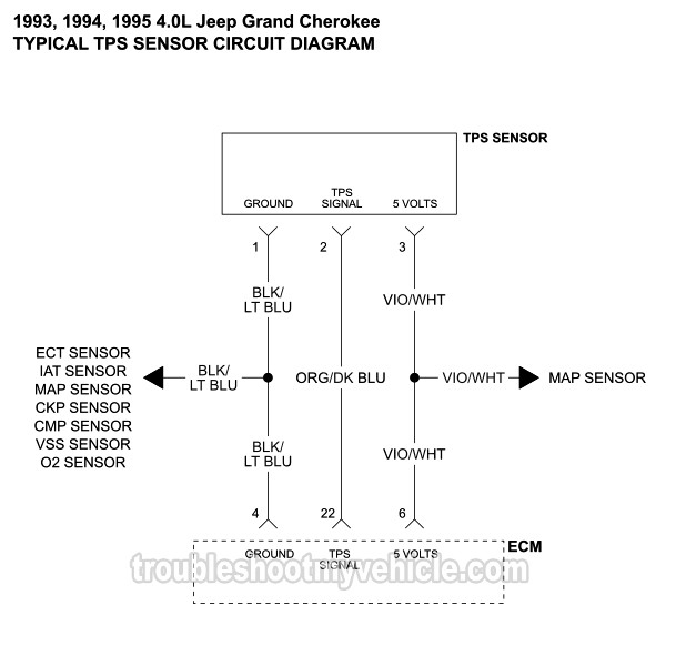
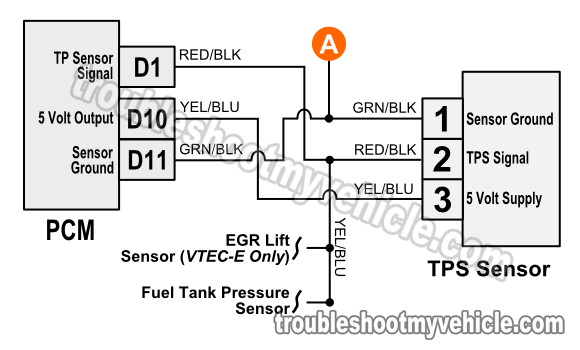
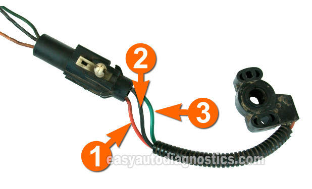
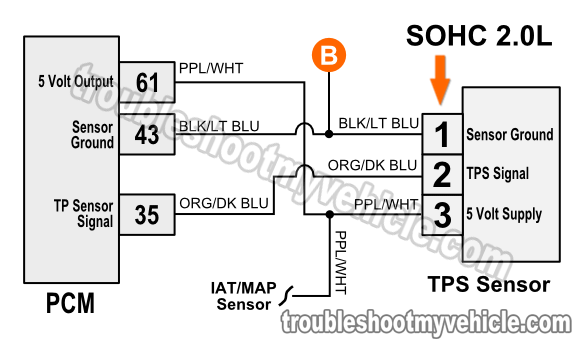
In modern throttle control systems, the throttle position sensor is used to detect the position of the throttle valve integrated into the actuator motor. A throttle position sensor or TPS is an accelerator pedal sensor without a pedal arm. Its electrical circuitry is the same as the accelerator pedal position sensor.
So, a 6 pin accelerator pedal position sensor wiring diagram is, two wires are for the earth, two for the input voltage, and two for signals back to the computer (ECU). Non-Contact Type Accelerator Pedal Position Sensor (APPS) The non-contact-type accelerator pedal position sensor is of hall effect and inductive type.
DIAGRAM 2: Accelerator Pedal Position (APP) Sensor Circuits. More 3.5L V6 Chevy Malibu Tutorials . If you need to test the electronic throttle body itself, check out this tutorial: Electronic Throttle Body Tests (2007-2009 3.5L Chevrolet Malibu And Pontiac G6) .
Im guessing the TB has to be removed, but do the TB sensors get removed individually? Such as the TPS amd APPS?
The P2138 trouble code is triggered when there are problems with the throttle/pedal position sensor/switch. However, it's not the only code related to the throttle body and its circuitry. The P2135, P2136, P2137, P2139, and P2140 DTCs also indicate issues in the same areas.
About Wiring Sensor Diagram Crankshaft Position . Removed the sensor, 10mm bolt. had my crank sensor stall engine in rush hour yesterday and it was a hat day here in the 90F. The 1999 Chevy Lumina 3. Chrysler wiring diagrams are designed to provide information regarding the vehicles wiring content. Accelerator Pedal Position Sensor.
Engine Model: Maxxforce Casting. Diagrama maxxforce 13 engine together with international prostar wiring diagram also le4n together with international maxxforce engine diagram in truck along with need a diagram for replacing the map sensor furthermore dd13 throttle pedal position sensor wiring diagram as well as 8yb9q international dte engine.
8 Dec 2008 — C6 Tech/Performance - Accelerator pedal position (APP) sensor wiring diagram - Anyone help? - Hello everyone, I'm looking for a wiring ...
Accelerator Pedal Position SensorDescribes the operation of the APP or accelerator position sensor. The APP sensor is found in almost every vehicle today. Th...
Troubleshooting the pedal position sensor is gonna be difficult. omgwtfbbq!, Apr 10, 2018 #6. Apr 10, 2018 at 12:18 PM ... I would download the schematics/block diagrams for the accelerator sensor circuits and start testing. ... it's possible you did something to a wire or have a bad ground (did you disconnect your battery or anything in the ...
Throttle Position Sensor Wiring Diagram – dodge throttle position sensor wiring diagram, ford throttle position sensor wiring diagram, gm throttle position sensor wiring diagram, Every electric structure is composed of various different components. Each part ought to be placed and linked to different parts in particular manner. Otherwise, the arrangement won’t work as it ought to be.
Dec 21, 2021 · Tps Wiring Harness | Wiring Diagram – Accelerator Pedal Position Sensor Wiring Diagram In addition, Wiring Diagram provides you with time frame in which the assignments are to become accomplished. You’ll be in a position to understand specifically once the tasks ought to be completed, which makes it easier for you personally to effectively manage your time and effort.
Trying to replace the Accel Pedal Sensor on my 01 Ex 7.3l to accomodate a tuner. The wiring harness for the tuner that is supposed to plug into accelerator sensor is a 10 wire single head and the accelerator on the Exc is a dual head accelerator with two smaller heads and only 5 wires combined.
Accelerator Pedal Position Sensor Wiring Diagram – wiring diagram is a simplified satisfactory pictorial representation of an electrical circuit. It shows the components of the circuit as simplified shapes, and the skill and signal links amongst the devices.
Hi need help finding a good App Sensor online for My 2007 Z.
The car seems to still show some of the symptoms of the bad wiring (fluctuating idle, some smoke sometimes), so now I need to check if my throttle actuator is in good condition, so I am looking for the pin designation on the throttle actuator's plug, or the internal diagram (or schematic) to make electrical tests to see if the throttle position ...











0 Response to "37 accelerator pedal position sensor wiring diagram"
Post a Comment