37 obd0 to obd1 wiring diagram
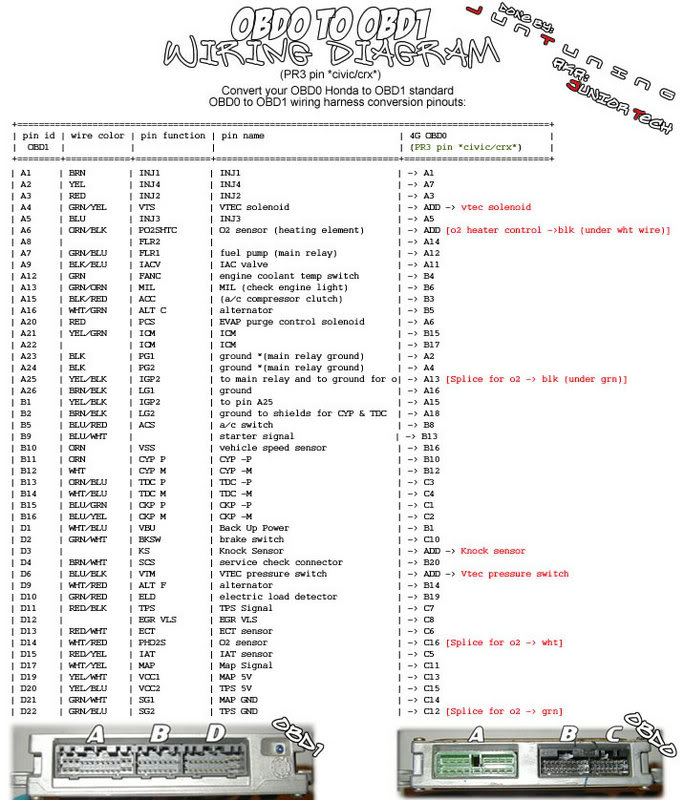
obd0 b16 wiring diagram. Jump to Latest Follow 1 - 11 of 11 Posts. B ... IMO go ahead and take this oppurtunity to buy a new harness, rywire obd0->obd1 eco conversion harness and run a p30 ecu. that way you can get chipped/dynotuned in the future while youre at it. '90 crx S i D16Z6, arp rod bolts, OBD1 conversion/chipped P28, ... Obd0 to Obd1 Wiring Diagram– wiring diagram is a simplified gratifying pictorial representation of an electrical circuit.It shows the components of the circuit as simplified shapes, and the capacity and signal contacts amongst the devices.
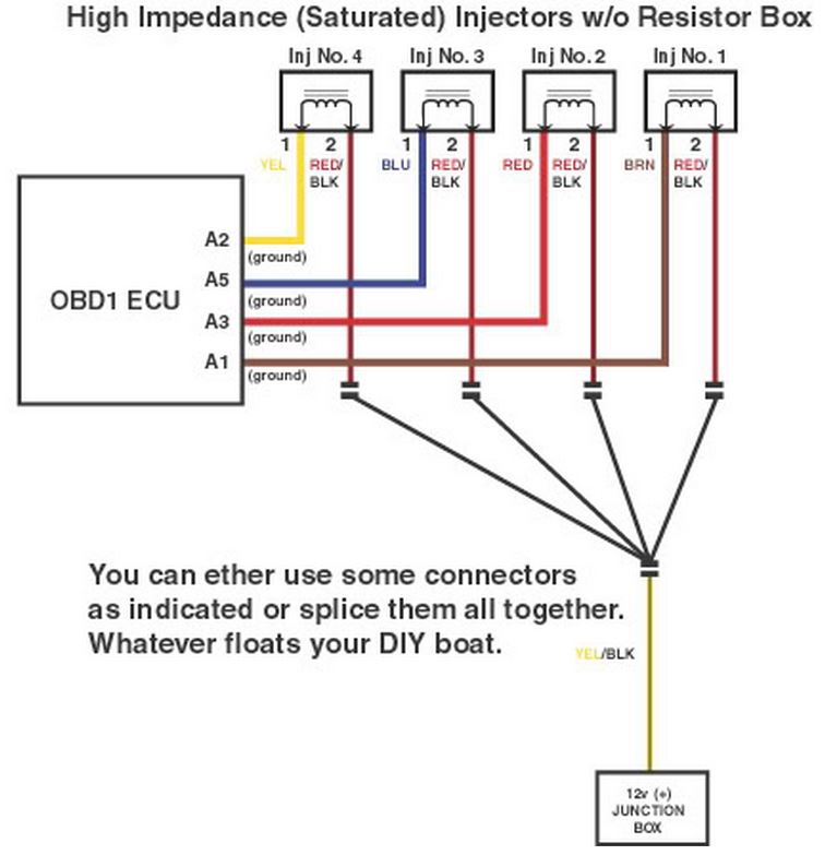
Nov 15, 2015 · If you can tell me what color wire goes to the obd1 Ecu plugs I can tell you what's it's for. Wiring the injectors is easy. Looking from the front the power wire to the left (pass side) and signal to the right. You will need to wire in a resister box for the obd0 injectors. 1.

Obd0 to obd1 wiring diagram
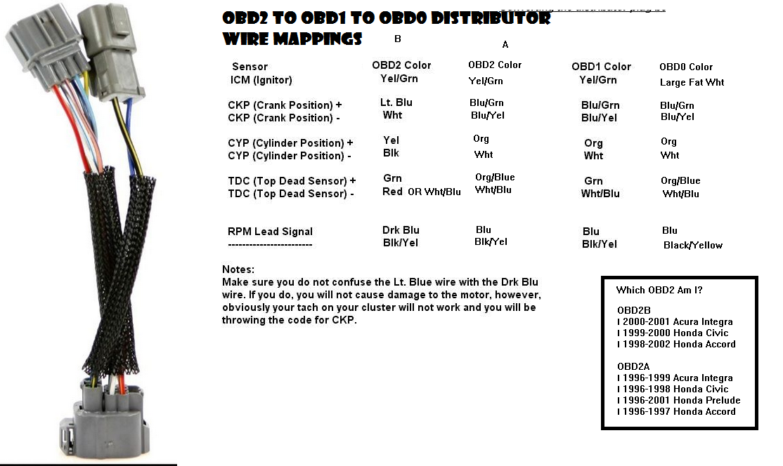
• Splice the OBD1/OBD2 engine harness distributor plug onto the OBD0 engine harness. For OBD1 distributors, all the wire colors match except one, see the chart on the diagram page that gives OBD1/OBD2 and OBD0 wire colors. • OBD0 and OBD1 distributor plugs have the same pin size for many of the wires. For the cleanest installation, you can de- Obd0 To Obd1 Wiring Diagram from static-cdn.imageservice.cloud To properly read a cabling diagram, one offers to learn how the components within the program operate. For example , when a module will be powered up and it also sends out the signal of fifty percent the voltage in addition to the technician does not know this, he would think he ... EACV (IACV) - 2-wire connector (if car was DPFI, the connector is These are the wire colors on the stock harness (most of them are the same.Obd0 to obd1 distributor wiring page 2 honda tech honda forum rh honda tech com Obd0 to obd1 distributor wiring page 2 honda tech honda forum rh honda tech com Dpfi to mpfi writeup hondaswap rh hondaswap ...
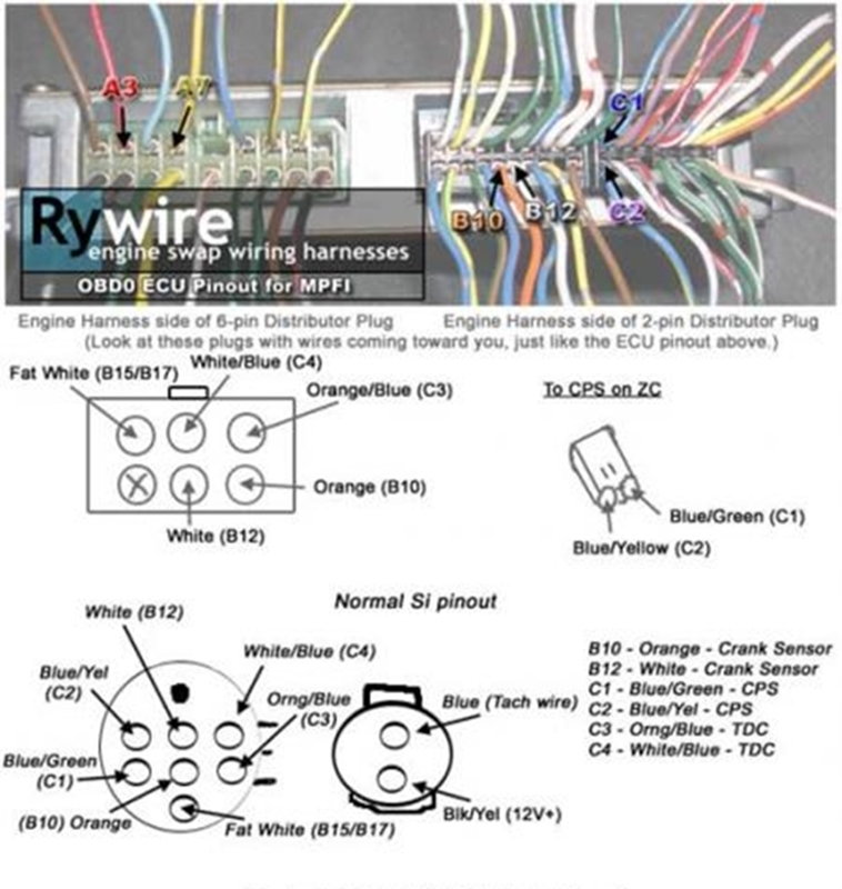
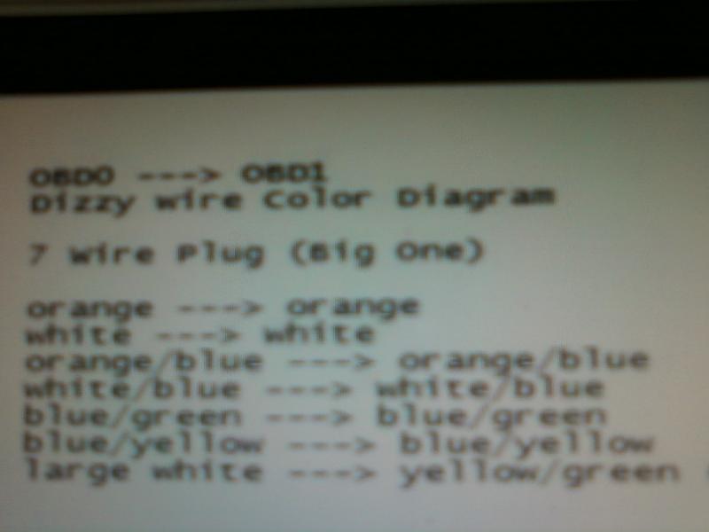
Obd0 to obd1 wiring diagram. This step is fairly easy, just match all the colors up. There should be 2 white wires that are on the OBD0 distributor plug and only one white wire on the OBD1 or OBD2 distributor plug, plus an extra yellow/green wire. The larger of the two white wires on the OBD0 side needs to go to the yellow/green wire on the OBD1/OBD2 distributor. 06.02.2019. 1 Comments. on Obd2a To Obd1 Distributor Wiring Diagram. This will adapt a OBD1 Distributor to plug into a + OBD2 position style Hondata CPR COP Harness · OBD0 to OBD2 8-Pin Distributor Adapter. Next up we'll be looking at the OBD2 distributor and wiring diagram in our How To Convert OBD2 to OBD1 walkthrough guide. Trying to find correct wiring diagrams is the problem I am facing. I think I have it sorted now however. I have a OBD1 P30 ECU for a B16a2, which is 92 to 95. The diagram I posted is the best one I had, and it is a complete diagram on one page, but the quality is just rubbish. Anywho I wired up the dizzys. I cut the obd0 plug and put it on the obd1 dizzy. I put in my 450cc dsms and pluged in my jumper and obd1 ecu. Now it just cranks and sparks every now and again. IDK can someone just give me some ideas cause im just really frustrated hence the long thread. haha. Heres the diagram I have.
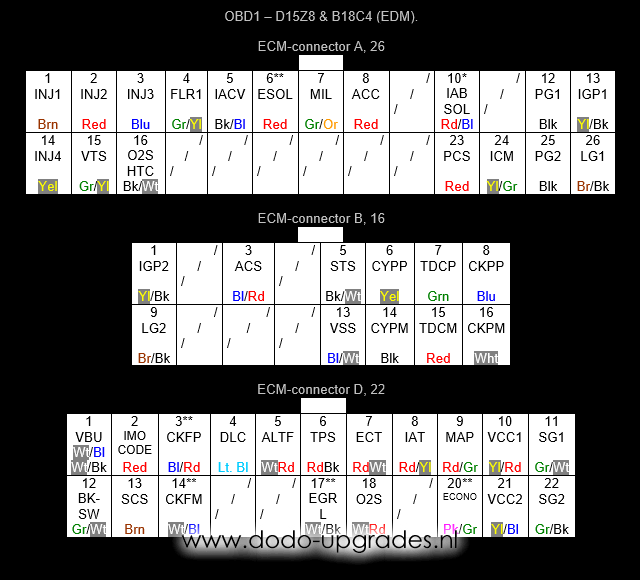
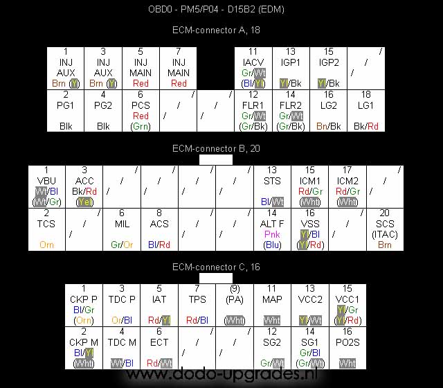
The OBDII Honda D and B. Obd1 to obd2 adapter wiring diagram along with toyota gt86 engine along with harness rywire b series engine moreover 85 camaro obd1 pinout diagram moreover engine coolant diagram moreover obd0 to obd1 distributor wiring diagram also f ke light switch wiring diagram as well as usb to obd2 cable wiring diagram as well as ... Honda Distributor Wire Colors OBD0, OBD1, OBD2. Honda Distributor Wire Colors.Oct 29, · honda obd1 alternator diagram html imageresizertool honda obd1 alternator diagram to her with tech area also obd0 to obd1 distributor wiring diagram moreover tech area to her with tech area further diagram. obd0 1 2 alternator plug wiring - ffs technet ... OBD0 PM6 Si Ecu Pinout 88-91 Civic Si. Crx Si, 90-91 Integra. OBD1 ECU Pinout Civic 92-95 Integra. These wires are the VTEC wire, the VTEC oil pressure wire and an O2 sensor wire. 2. Cut off the OBD0 ECU wire plugs and splice the wires from the OBD1 ECU plugs to the wires from the OBD0 harness as listed below. You will also have to attach the 3 extra wires as mention above in #1. Here is the information on the wiring the OBD1 ECU. It is originally by StorminMatt from CRX Resource. There are several additions that have been made to the listing in the hope of making it more helpful and easy ...
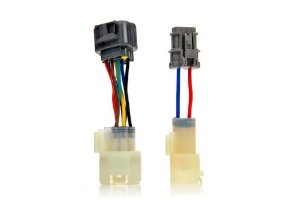
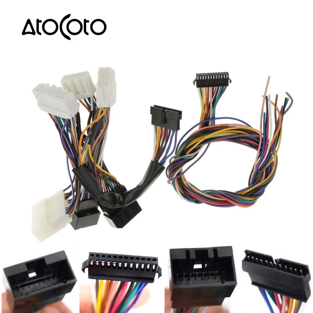
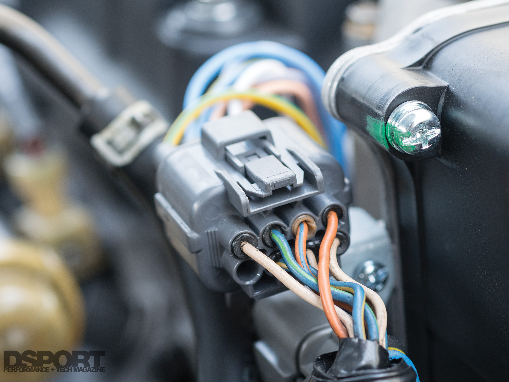
The following instructions will assist you in completing your installation of your *SSR OBD-0 to OBD-1 ECU conversion harness. Some additional plugs may be required, such as the OBD-1 or OBD-2 distributor plugs and the 4-wire 02 sensor plug. Other plugs, such as the VTEC solenoid plug, VTEC pressure switch plug and knock sensor plug may be ... If you need more details, do a search on google for "pr3 pinout" or "pw0 wiring pinout" or something along that line. I did a search and got more than one version of pinouts for the pr3. I think there's an obd0 and an obd1 pr3(i hear, not sure), so that could be why. But, good luck. OBD0/1/2 Alternator Plug Wiring. Certain Honda engine swaps require changes to the alternator connector. OBD0 and OBD1 B/D-series engines and wiring use the same 4-wire round alternator plug, so they are compatible with each other ie. plug n' play. OBD2 B/D-series alternators on the other hand use a 4-wire  rounded square plug and are ... harness. For OBD1 distributors, all the wire colors match except one, see the chart on the diagram page that gives OBD1/OBD2 and OBD0 wire colors. OBD0 and OBD1 distributor plugs have the same pin size for many of the wires.
I'm talking about the pins. I have an OBD0 and an OBD1 plug in front of me, all the wire colors match up between them except the OBD0 has two white wires and the OBD1 has one white wire and one yellow/green wire. His red wire is white on my plug. He has it going to the white/blue on the OBD1?!! It should be going to his yellow/black.
Hey anyone know where I can find the Wiring Diagram for the OBD0 to OBD1 Harness ? I have a OBD1 harness and a OBD0 Plug so I can make it. Thanks
OBD1 or OBD2 distributor that fits onto your engine. OBD1 ECU; OBD1 or OBD2 injectors and injector clips (optional - you can use the stock injectors with the stock injector resistor box). 4-wire O2 sensor (optional - if you are using a chipped/programmable OBD1 ECU with O2 sensor disabled you do not need to wire in a 4-wire O2 sensor) 1.
One of the differences between the OBD0 B16A and an OBD1 B-Series motors is the fact that you have to convert from two 1-wire oxygen sensors to one 4-wire oxygen sensor with heated wires. In order for the ECU to operate correctly, you will need to place the new sensor downstream from the original locations so that it can read all four cylinders.
EACV (IACV) - 2-wire connector (if car was DPFI, the connector is These are the wire colors on the stock harness (most of them are the same.Obd0 to obd1 distributor wiring page 2 honda tech honda forum rh honda tech com Obd0 to obd1 distributor wiring page 2 honda tech honda forum rh honda tech com Dpfi to mpfi writeup hondaswap rh hondaswap ...
Obd0 To Obd1 Wiring Diagram from static-cdn.imageservice.cloud To properly read a cabling diagram, one offers to learn how the components within the program operate. For example , when a module will be powered up and it also sends out the signal of fifty percent the voltage in addition to the technician does not know this, he would think he ...
• Splice the OBD1/OBD2 engine harness distributor plug onto the OBD0 engine harness. For OBD1 distributors, all the wire colors match except one, see the chart on the diagram page that gives OBD1/OBD2 and OBD0 wire colors. • OBD0 and OBD1 distributor plugs have the same pin size for many of the wires. For the cleanest installation, you can de-









0 Response to "37 obd0 to obd1 wiring diagram"
Post a Comment