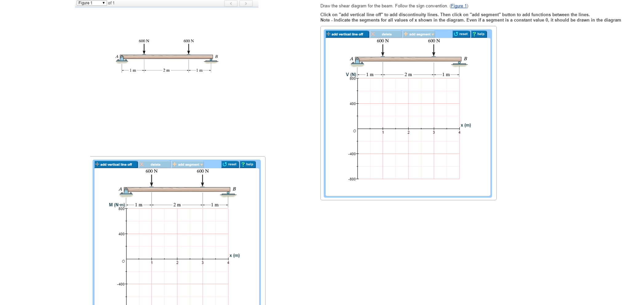
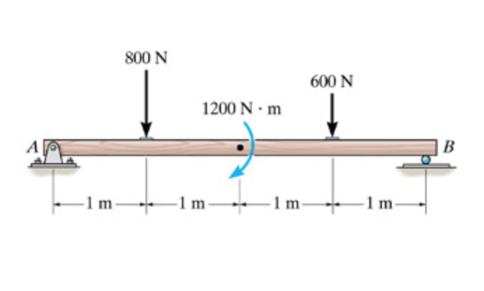
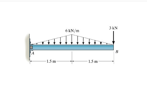
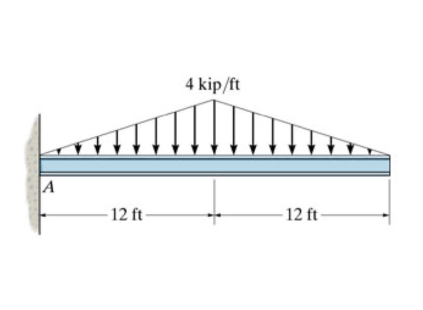
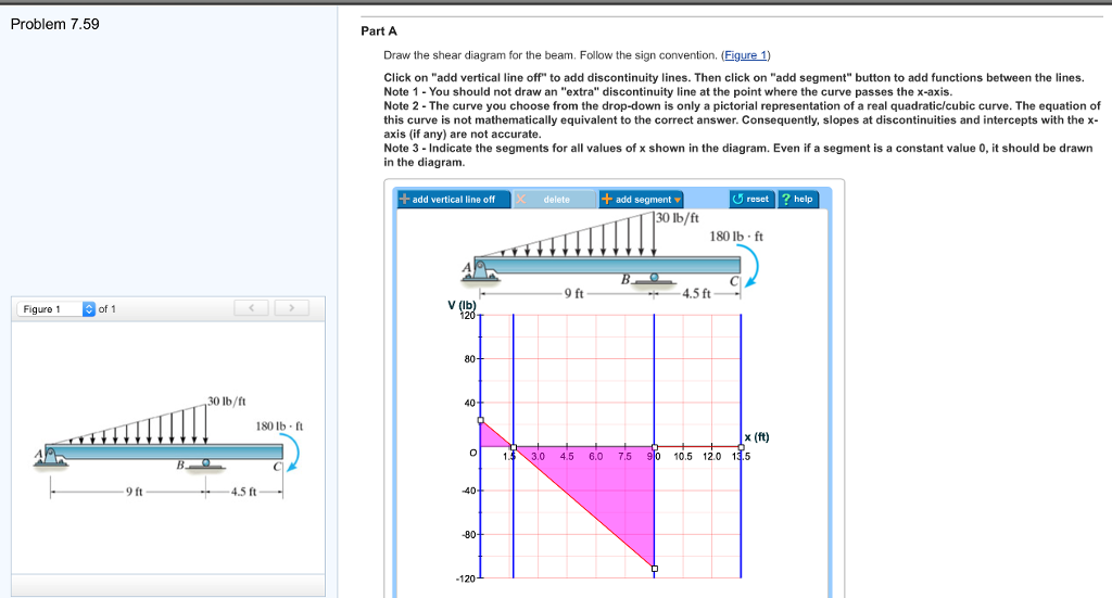
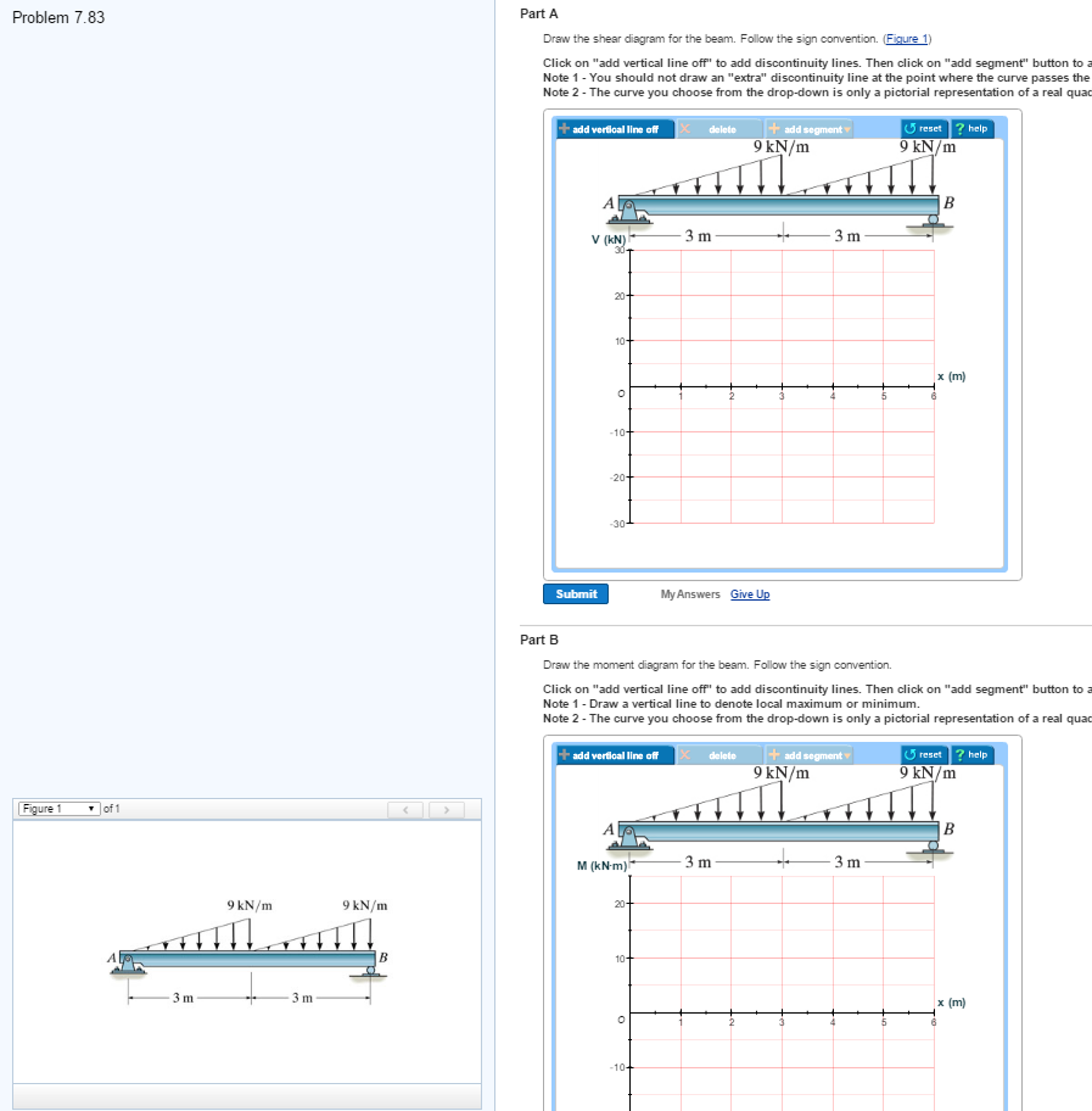
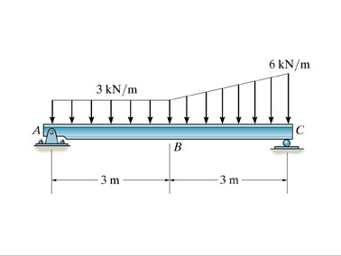
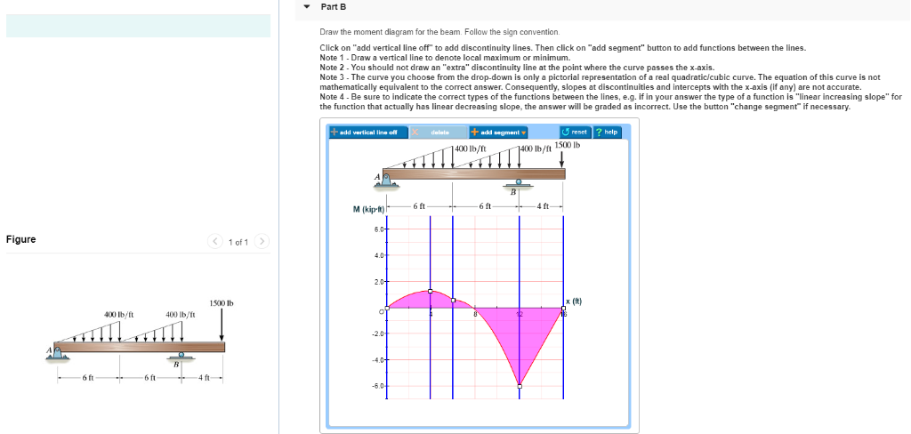
38 draw the shear diagram for the beam. follow the sign convention. (figure 1)
Materials Engineering Science Processing ... - Academia.edu Materials Engineering Science Processing and Design.pdf Torque Questions and Answers - Study.com A beam resting on two pivots has a length of L = 6.00 m and mass M= 78.7 kg. The pivot under the left end exerts a normal force n_1 on the beam, and the second pivot placed a distance l …
SIXTH EDITION ADVANCED MECHANICS OF MATERIALS - … Academia.edu is a platform for academics to share research papers.
Draw the shear diagram for the beam. follow the sign convention. (figure 1)
MECHANICS OF MATERIALS Pages 1-50 - Flip PDF ... - FlipHTML5 20.10.2017 · A simple sign convention for shear stresses does not exist; a convention that depends on a coordinate system will be introduced later in the text. If the stresses are uniformly distributed, Eq. (1.2) gives P V (1.3) s¼A t¼A where A is the area of the cross section. If the stress distribution is not uni- form, then Eqs. (1.3) should be viewed ... Part A Draw the shear diagram for the beam ... - HomeworkLib Part A Draw the shear diagram for the beam. Follow the sign convention. (Figure 1) Click on "add vertical line off" to add discontinuity lines. Then click on " ...1 answer · 0 votes: 6 ft 3ft Shear force diagram (kip) -7.50 Mmax=2.45 Bending moment diagram (kip-ft) EMA = 0: - (3 *6/2) * (6 - (1/3)*6) + R$*6 - 2*3*(6 + 3/2) = 0 Rp ... Strength of Materials - Indian Institute of Technology Madras Each figure should be called by the text. ... booklet follow the above sign convention. In drawing the shear force diagram and bending moment diagrams various sign conventions are used by different authors. The following sign convention is adopted in this booklet and the flexure formula needs to be interpreted based on this sign convention. Force or moment in …
Draw the shear diagram for the beam. follow the sign convention. (figure 1). Design Constraints in Engineering: Definition & Example ... 23.01.2022 · Follow the sign convention. b) Draw the moment diagram for the beam. Follow the sign convention. Determine the maximum deflection of the simply supported beam. The beam is made of wood having a ... Part A Draw the shear diagram for the beam ... - Study.com Answer to: Part A Draw the shear diagram for the beam. Follow the sign convention. (Figure 1) Part B Draw the moment diagram for the beam. Follow...1 answer · Top answer: Since the load is uniformly distributed, the supports will have the same value of reaction force. At the roller support, the reaction is: 12×3×300=90012×3 ... Strength of Materials - Indian Institute of Technology Madras Each figure should be called by the text. ... booklet follow the above sign convention. In drawing the shear force diagram and bending moment diagrams various sign conventions are used by different authors. The following sign convention is adopted in this booklet and the flexure formula needs to be interpreted based on this sign convention. Force or moment in … Part A Draw the shear diagram for the beam ... - HomeworkLib Part A Draw the shear diagram for the beam. Follow the sign convention. (Figure 1) Click on "add vertical line off" to add discontinuity lines. Then click on " ...1 answer · 0 votes: 6 ft 3ft Shear force diagram (kip) -7.50 Mmax=2.45 Bending moment diagram (kip-ft) EMA = 0: - (3 *6/2) * (6 - (1/3)*6) + R$*6 - 2*3*(6 + 3/2) = 0 Rp ...
MECHANICS OF MATERIALS Pages 1-50 - Flip PDF ... - FlipHTML5 20.10.2017 · A simple sign convention for shear stresses does not exist; a convention that depends on a coordinate system will be introduced later in the text. If the stresses are uniformly distributed, Eq. (1.2) gives P V (1.3) s¼A t¼A where A is the area of the cross section. If the stress distribution is not uni- form, then Eqs. (1.3) should be viewed ...












0 Response to "38 draw the shear diagram for the beam. follow the sign convention. (figure 1)"
Post a Comment