40 how to draw phasor diagram
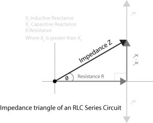
Steps to draw the phasor diagram of the rlc series circuit. phase angle. power in rlc series circuit. impedance triangle of rlc series circuit. the rlc circuit is shown below: in the rlc series circuit. xl = 2πfl and xc = 1 2πfc. when the ac voltage is applied through the rlc series circuit the resulting current i flows through the circuit. Draw the phasor diagram representing the circuit currents.(3marks) The resonant frequency.(2marks) Describe each of the following processes of making a permanent magnet. (4marks) Heating; Stroking; With an aid of a well labelled diagram ,explain how a relay operates in high current load.(9marks)
Here are a number of highest rated Three Phase Phasor Diagram pictures upon internet. We identified it from obedient source. Its submitted by meting out in the best field. We tolerate this nice of Three Phase Phasor Diagram graphic could possibly be the most trending subject later than we allocation it in google plus or facebook.

How to draw phasor diagram
diagram from scratch, you have to go for the software's electrical engineering or electrical design section. The second step is to get all symbols an inverter needs. RC Circuit: Formula, Equitation & Diagram | Linquip Aug 24, 2021 · Steps To Draw a Phasor Diagram for an RC Circuit. Current I Updated date: Jun 28, 2021 How to Understand Electricity: Volts, Amps, Watts and Electrical Appliances Author: Eugene Brennan Eugene is a qualified control... A simplistic model of an atom, known as the Rutherford–Bohr model or Bohr model or Bohr diagram has a central nucleus made up of particles called protons and neutrons.... Electrical Tutorial about Transformer Loading and transformer on load characteristics including phasor diagrams and transformer losses
How to draw phasor diagram. Draw the closed voltage phasor diagram for the system, showing all l-l and l-n voltages. C) determine the phasor value of the line currents. D) determine the phasor value of the phase currents in the source and the load. E) calculate the complex power s that is consumed by the load and draw the power triangle. F) what is the power factor of the ... 11 September 2013 GE Measurement & Control Phasor XS Portable Phased Array Ultrasonic Flaw Detector User’s Manual 021-002-362 Rev. 11 September 2013 www.ge-mcs.com ©2013 General Electric Company. All rights reserved. Technical content subject to change without notice. [no content intended for this page - proceed to next... Phasor Diagrams, drawing phasor diagrams and using phasor diagrams to show phase difference. Feb 24, 2012 · Step 1 : Draw a phasor diagram for given circuit. Step 2 : Use Kirchhoff's voltage law in RLC series circuit and current law in RLC parallel circuit to form differential equations in the time-domain. Step 3 : Use Laplace transformation to convert these differential equations from time-domain into the s-domain.
I am trying to comprehend GMSK modulation/demodulation. IQ samples are being phase keying is such a way that after multiplying them by complex carrier and sum both I and Q together, there is FM modulation. I don't understand how its being done. I guess it must be trigonometry but can someone explain me how phase changes in IQ... A rotating phasor on the IQ plane... see diagram below). So the phase... How to draw a “halftone” spiral... Draw the phasor diagram. (3 marks) MARKING SCHEME . Procedure of connecting an ammeter to take measurements in a circuit . Turn - off the power; Ammeter should be connected in series with the load current. Observe polarity. Select the range starting from the highest. Nominal resistance Orange Black 30 Brown x 10 1 = 300 I hacked the following drawing together. This makes it very difficult to colour the areas marked: 1.x.x, 2.x.x, 3.x.x, 4.x.x, 5.x.x, 6.x.x, 7.x.x and 8.x.x . In essence I would like to know how ... How To Draw Phasor Diagram. Stages Of Conflict Management. 3d Scan Studio. Email Me Meme. Knows Too Much Meme. Poems For Niece Funeral. Adorable Stitch Drawing. Gateway Of Grand Blanc. Minuteman Missile Historic Site. Dying Quotes Inspirational. Ford Racing 460 Crate Engine. Walther P22 Grips.
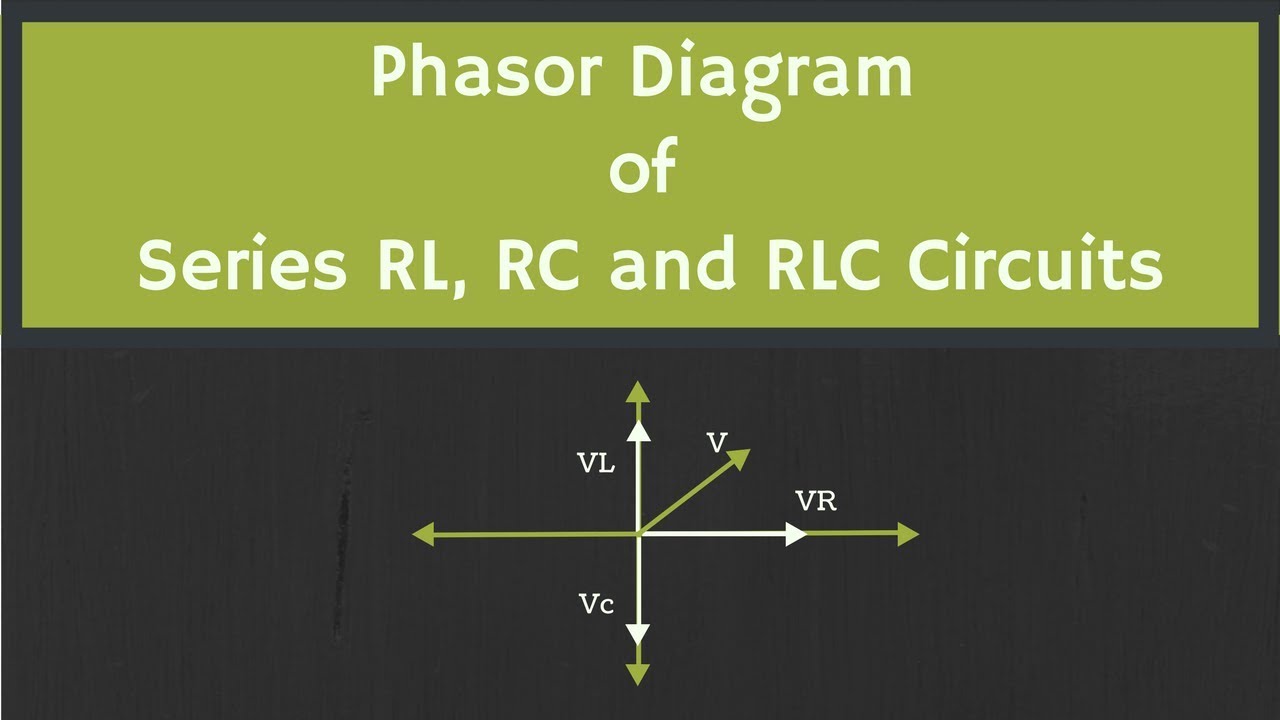
The phasor diagram of series RLC circuit is drawn by combining the phasor diagram of resistor, inductor and capacitor. Before doing so, one should understand the relationship between voltage and electric current in case of resistor, capacitor and inductor. Example 1: RLC circuit is series. Example 1: Consider RCL circuit in series. Introduction A Magnitude Plot A Phase Plot A more generic derivation Making a Bode Diagram A Constant Term... By drawing the plots by hand you develop an understanding about how the locations of poles and zeros effect... individual phasor is fairly straightforward. The difficulty lies in trying to draw the magnitude and phase... shows how a first order pole... used to draw different elements of a Bode diagram. A synopsis of these... Two impedances are connected in parallel to the supply, the first takes a current of 40 A at a lagging phase angle of 30°, and the second a current of 30 A at a leading phase angle of 45°. Draw a phasor diagram to scale to represent the supply voltage and these currents. From this diagram,... Phasor Diagram Of Rlc Series Circuit Diagram Media. How to draw phasor diagram. here are a number of highest rated how to draw phasor diagram pictures upon internet. we identified it from well behaved source. its submitted by government in the best field. we allow this nice of how to draw phasor diagram graphic could possibly be the most trending topic similar to we ration it in google plus or.
Phasor and The Phasor Diagram in AC Circuits Explained
Exhaust diagram and system - ClubLexus - Lexus Forum Aug 24, 2021 · Steps To Draw a Phasor Diagram for an RC Circuit. Current I is considered as reference and voltage reduction in resistance is (V R).So, V R = IR is drawn in phase with the current I. Voltage reduction in capacitive reactance

Phasor Diagram - an overview | ScienceDirect Topics
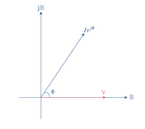
4. What is Phasor? Phasor is nothing but a vector that is rotating at a constant angular velocity. The length of the phasor or vector represents the magnitude of alternating quantity and the arrow indicates the direction of the vector. 5. Draw the phasor diagram for pure inductance, pure capacitance, and Resistance? Pure Resistance. Pure ...

Phasor diagram in Android - Stack Overflow
Rc Circuit Phasor Diagram. Here are a number of highest rated Rc Circuit Phasor Diagram pictures upon internet. We identified it from reliable source. Its submitted by organization in the best field. We take on this nice of Rc Circuit Phasor Diagram graphic could possibly be the most trending topic next we ration it in google improvement or ...

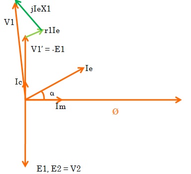
PHASOR DIAGRAM ( INDUCTIVE LOAD) FOR A SINGLE PHASE TRANSFORMER
How to draw a Phasor diagram - Learn.org.au Dear Twitpic Community - thank you for all the wonderful photos you have taken over the years. We have now placed Twitpic in an archived state. Survey XII: Digital New Normal 2025 - After the Outbreak Lab Manual For Digital Fundamentals

Draw a phasor diagram to represent the current and supply ...
Drawing Basic phasor diagram This code shows how to draw a basic phasor and use plot windows. A wiring diagram is a streamlined standard pictorial depiction of an electrical circuit. Example Image Wiring Diagram Auto Diagram, Electrical Simply click on the image above to download. Wiring diagram drawing tool. Free drawing software for Windows, Mac […]
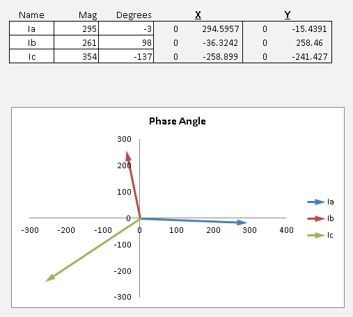
Excel Phasor Diagram Builder
Here are a number of highest rated How To Draw Phasor Diagram pictures on internet. We identified it from honorable source. Its submitted by meting out in the best field. We tolerate this nice of How To Draw Phasor Diagram graphic could possibly be the most trending subject with we allowance it in google improvement or facebook.
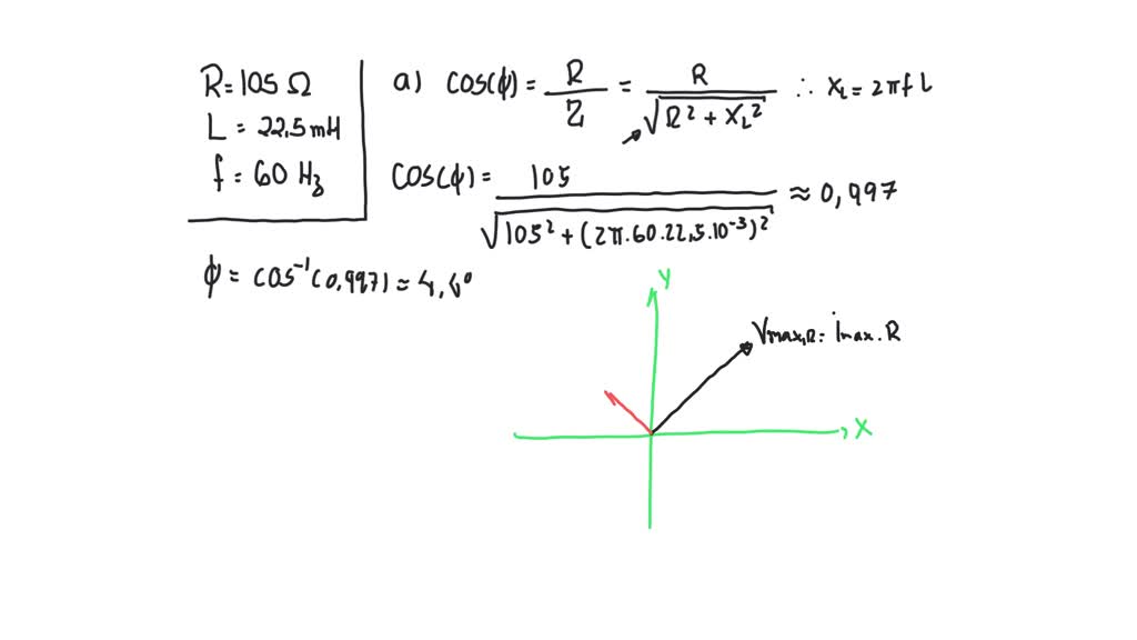
a sketch the phasor diagram for an ac circuit with a 105 omega resistor in series with a 225 mh indu
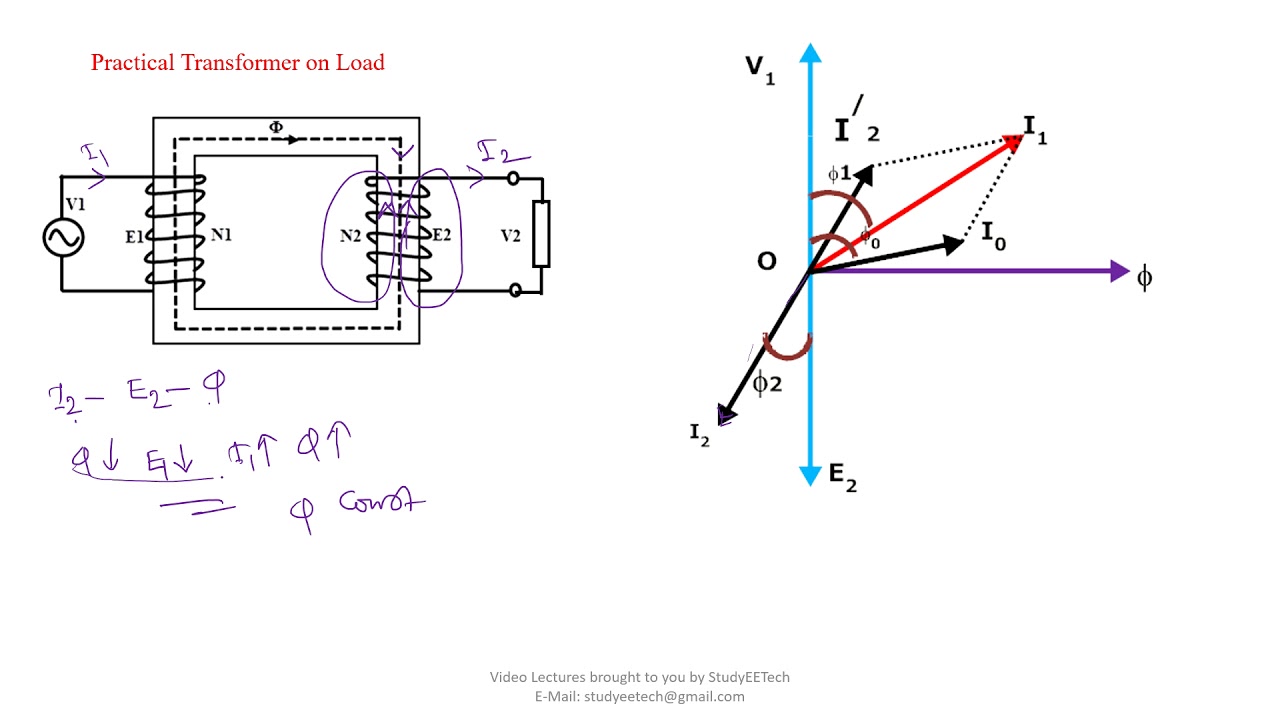
Code: AEIO PART - 111 Subject: ELECTRICAL ENGINEERING DESCRIPTIVES Q.l Draw and explain the phasor diagram of a transformer on load at a lagging power factor. Ans: (D) (7) Fig. AAI 1 Fig. AA2 12 4) Fig AA2 shows the phase diagram of a transformer on a load at lagging power factor and corresponds to the equivalents circuit of transformer (Fig
How to Draw Transformer Phasor Diagram
Last time, we discussed how to customize and compile the NodeMCU firmware from source using open source tools. Assuming a working NodeMCU installation, we're now going to explore some of the actual functionality of the device and begin interacting with both the "internet" and "things" aspects of IoT. Starting with a fresh...

Phasor Diagram and Phasor Algebra used in AC Circuits
Draw the circuit diagram, waveform of voltage and current, phasor diagram of (i) purely resistive circuit (ii) purely inductive circuit (iii) purely capacitive circuit, supplied by sinusoidal voltage.
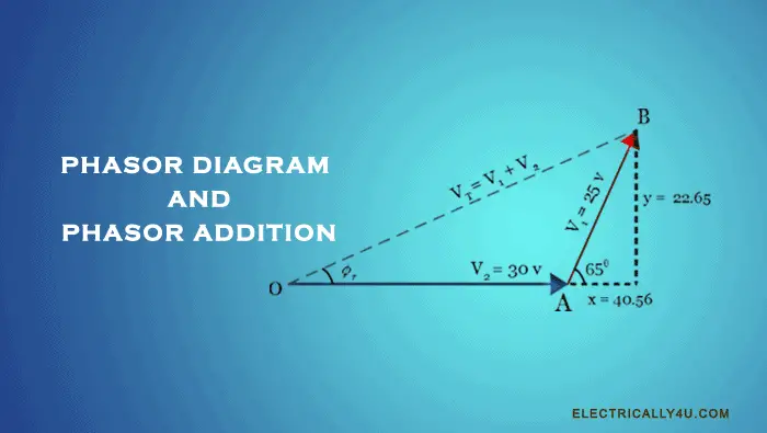
Phasor Diagram and Phasor Addition
Phasor Diagram for Unity Power Factor. Let us consider the synchronous motor is drawing the current from the supply at the unity power factor. By considering equation(3), the phasor diagram is drawn. Draw the terminal voltage as the reference phasor, such that OA = V. For unity power factor, the armature current is in phase with the voltage.

Phasor Diagram and Phasor Algebra used in AC Circuits
This is not the case of a multiplication of two complex phasors, so we can use it "as is" to express the final resulting complex phasor. Equation (2c) is similar to Equation (1f) above for AM modulation, except that there is an " " before the modulation term, indicating a 90° phase sift between the carrier and modulation. This...

Phasor diagrams and Impedances
MANUALHow to draw a Phasor diagram - Learn.org.auMotorola A1000 service manual - CPKB - Cell Phone ACS 500 Programming Manual - ABBAuto Repair Manual Forum - Heavy Equipment Forums AutoCAD Electrical from beginner to expert - TutorialspointGuidance Manual for Constructed Wetlands - GOV.UKschematics:console_related_schematics [NFG Games ...
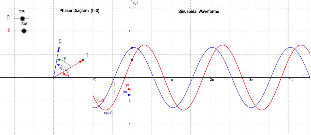
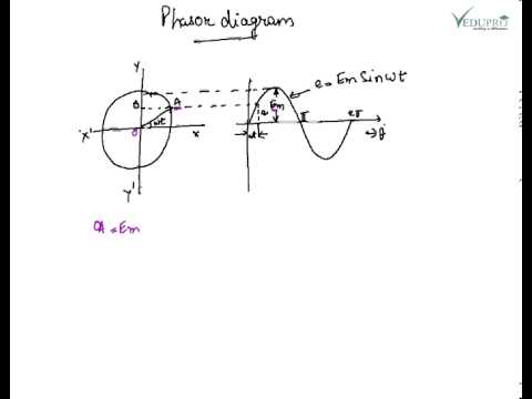
Phasor Diagram and Sinusoidal Waveforms – GeoGebra
We use log-spline densities to estimate marginal distributions of phasor measurements and fold these into a multivariate Gaussian copula to capture important correlations. Sensitivity to outages varies according to which line goes down and where PMUs are placed on the grid. A greedy search algorithm is demonstrated for placing...

Phasor Diagram and Phasor Algebra used in AC Circuits
Electrical Tutorials about how a Phasor Diagram can be used to show the phasor relationship between a voltage and a current in a sinusoidal function
What is the transformer phasor diagram? - Quora
How To Draw Phasor Diagram. Here are a number of highest rated How To Draw Phasor Diagram pictures upon internet. We identified it from well-behaved source. Its submitted by government in the best field. We allow this nice of How To Draw Phasor Diagram graphic could possibly be the most trending topic similar to we ration it in google plus or ...

Phasor Diagram for Star connection - YouTube
PaperHow to draw a Phasor diagram - Learn.org.au(PDF) Basic Electrical Installation Work, Fourth Edition Find Jobs in Germany: Job Search - Expat Guide to Germany BPEC
Phasor Diagram of Transformer - Electrical Concepts
For this circuit.. a. Find the total Admittance Yt in polar form b. Draw the admittance diagram c. Find the voltage E and the current Ig and Ic in phasor form d. Draw the phasor diagram of the current Ir, Ig and Ic e. Verify Kirchoffs current law at one node f. Find the average […]

Phasor Diagram and Phasor Algebra used in AC Circuits
Here are a number of highest rated How To Draw A Phasor Diagram pictures upon internet. We identified it from obedient source. Its submitted by handing out in the best field. We assume this nice of How To Draw A Phasor Diagram graphic could possibly be the most trending subject later we allocation it in google gain or facebook.

Phasor Diagram of Series RLC Circuit
Draw the schematic representations of a shell type transformer and a core type transformer. Which one of the two is suitable for use as a distribution transformer and why? (a) Explain with reasons as to why transformer core is made up of silicon steel laminations. (b) Draw the phasor diagram of a single-phase transformer for lagging power ...
Autotransformer phasor diagram | Physics Forums
To draw the phasor diagram of a reactive circuit having a number of branches connected in parallel across a common voltage, which of the following is more convenient to use as the reference phasor? (A) Circuit Current (B) Branch Current (C) Source Voltage (D) Input power

Phasor Diagram - an overview | ScienceDirect Topics
Editor’s note: This story is the third in the Map to the Middle Class series from The Hechinger Report, examining how schools can prepare students for the good... system to a phasor coordinate system would help them check their work in the field. “I was thinking it was going to be a lot easier. I had to slap myself in the...
Phasor Diagrams and Phasor Algebra - Electronics-Lab.com
labels to be and . +1 for using the angles library for that. @marmot, thank you very much. in school we use symbols as you suggested, however for (to me unknown) reason are in latex defined symbols and and i just use... i sow them in some old german books. where is more appropriate to ask from they originate, here or on "metaTeX"?
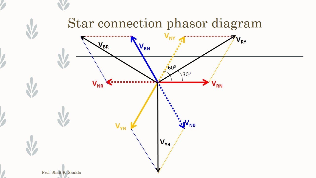
Three Phase AC Star Circuit Phasor Diagram
If the synchronous reactance is 5 ohms/phase and the resistance is negligible, draw the phasor diagram and calculate the value of the generated emf and the load angle. (ii) If the excitation is reduced by 10% and, as a consequence the generated e.m.f. is reduced by 10%, calculate the new value of the generated e.m.f E , the stator current, the ...

Phasor Diagram for AC Series Motor | Electrical4U
The Best and Completed Full Edition of Diagram Database Website You Can Find in The Internet ... Jayco Camper Wiring Diagrams Diagram For Door Lock Actuators Wiring Diagram 240 Single Phase Motor Wiring Diagram To Point Wiring Diagram Software Jeep Cherokee Brake Light Wiring Diagram Guides Wiring Diagrams Autozone Cycle Diagram Of Steps Ranger Truck Service Shop Repair Set Oem Books Factory 02 Volume Set Electrical And Vacuum Wiring Diagrams And The Powertrain Control Eng Schematic Diagram Wire Diagram For Wiring A Timer Acura Tl Wiring Diagram Diagram For Strat Capacitors 12 Major Scales
Phasor and The Phasor Diagram in AC Circuits Explained
I saw the image below and noticed that whoever made it slanted the angle label to match the slant of the perspective. I think this is a really nice effect that very effectively labels angles in 3 dimensional shapes. I was wondering how this kind of effect is done. Also, I was wondering how the slanted right-angle sign is done.5 how to draw a phasor diagram (like this picture) 3 Drawing a diagram with arc and angle 6 how to draw the...

Phasor diagram of the FM signal, SS interference and noise at ...
Electrical Tutorial about Transformer Loading and transformer on load characteristics including phasor diagrams and transformer losses

Phasor Diagram and Phasor Algebra used in AC Circuits
Updated date: Jun 28, 2021 How to Understand Electricity: Volts, Amps, Watts and Electrical Appliances Author: Eugene Brennan Eugene is a qualified control... A simplistic model of an atom, known as the Rutherford–Bohr model or Bohr model or Bohr diagram has a central nucleus made up of particles called protons and neutrons....
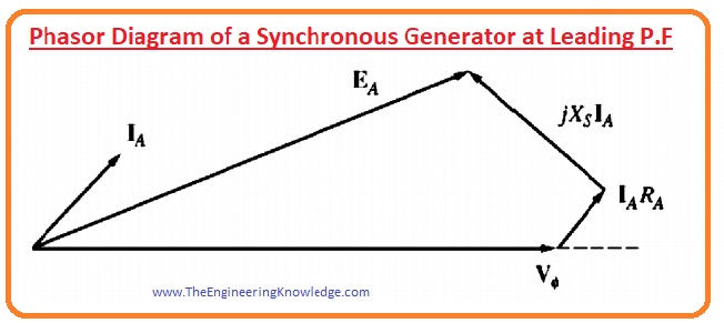
Phasor Diagram of a Synchronous Generator - The Engineering ...
diagram from scratch, you have to go for the software's electrical engineering or electrical design section. The second step is to get all symbols an inverter needs. RC Circuit: Formula, Equitation & Diagram | Linquip Aug 24, 2021 · Steps To Draw a Phasor Diagram for an RC Circuit. Current I
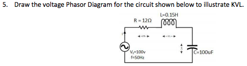
Solved 5. Draw the voltage Phasor Diagram for the circuit ...

Phasor Diagram and Phasor Algebra used in AC Circuits ...
Phasor Diagram, How to draw a Phasor Diagram ......

Phasor Sum - an overview | ScienceDirect Topics
RLC Series circuit, phasor diagram with solved problem

Creating Phasor Diagrams with Circuit Magic

3. Draw phasor diagram under resonance.​ - Brainly.in

Phasor Diagram - an overview | ScienceDirect Topics

i(t) i Elt) ---- T/8 T/4 Draw a phasor diagram to represent ...

22.6 Phasor Diagrams

In a RLC series circuit, the phasor diagram below shows ...

Electrical Phasor Diagrams | Electrical Academia
0 Response to "40 how to draw phasor diagram"
Post a Comment