40 stearns brake wiring diagram
24.01.2020 · Stearns Brake Wiring Diagram Eyelash Me . Stearns Brake 1 048 161 00 Bq Nema 2 208 230 460 3 Phase . Diagram Dc Motor Internal Wiring Diagram Full Version Hd . Bodine Electric N4698 Right Angle Dc Gearmotor 06 Hp 24vdc 63 Rpm . Leeson 5 Hp Brake Motor 3 Phase 1800 Rpm 230 460 V 184tc Frame Tefc 132480 00 . Top 10 Most Popular Motor … Stearns Brake Wiring Diagram / Gruppundstahl Com - Luckily, there are some places that may have just what you need. Trying to find the right automotive wiring diagram for your system can... Verbo Ser Worksheet - Verbo Ser O Estar English Esl Worksheets For Distance Learning And Physical Classrooms -
- The brake engages when power is removed from the motor - The brake applies force to an object in motion until friction either slows or stops the motion. - Motor slows and finally stops To Prevent MotionTo Prevent Motion - Brake engages after motor has come to complete stopto complete stop - Brake merely holds motor to prevent rotation.
Stearns brake wiring diagram
Stearns Brakes Replacement Parts Item Number 003452400 Part Number 003452400 Overview Documents Product Description : Stearns Brakes 003452400 LOCTITE #242 .5 ML CAPSUL Learn More $5.72 Add to Cart Call for Availability Stearns Brakes Replacement Parts Item Number 10703120 Part Number 10703120 Overview Documents Re: bedroom slide brake issue. Best approach is to bring slide in and then reattach the brake to hold the slide in place. The brake needs a full 12v+ to operate and the wiring from the switch the slide mechanism has a number of connections that can offer resistance. Try the slide after the generator runs a bit to ensure a full 12v. Stearns Brake. Failure to comply with these instructions could cause injury to personnel and/or damage to property if the brake is installed or operated incorrectly. For definition of limited warranty/liability, contact Rexnord Industries, LLC, Stearns Division, 5150 S. International Dr., Cudahy, Wisconsin 53110, (414) 272-1100. Caution 1. Installation and servicing must be made …
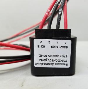
Stearns brake wiring diagram. brake is installed or operated incor-rectly. ... available at www.stearnsbrakes.com. ... Remove housing and disconnect power and wiring to coil. Stearns Brake Stearns Super-Mod 110VAC Clutch Brake 2-35-0561-01-ANL. Model SM-50-1020T 3 Apr 2009 — sufficient time for brake to cool before disassembly. ... Disconnect solenoid coil lead wires ... diagram on solenoid frame. 17 Nov 2010 — Brake. Failure to comply with these instructions ... Stearns Series 65,300 is a spring-set, ... leads) is shown in the wiring diagram,.
for 87,000 & 87,100 Series Self-Adjust Brakes (rev. B) ... liability, contact Rexnord Industries, LLC, Stearns ... All wiring and electrical connections. No. 8 AC Coil Kit Single and Dual Voltage Coils Series 67,000 and 77,000 Brakes: P/N 8-078-950-00 Dated 12/1/03: Wiring and Service Instructions DC Voltage Coils 5X,XXX and 8X,XXX Series: P/N 8-078-956-01 Dated 8/20/99 ... Rexnord Stearns Spring-Set (Power-Off) Motor Brakes Solenoid Actuated Brakes NEMA C-Face Mount. Solenoid Actuated Brakes ... Brake. Failure to comply with these instructions ... liability, contact Rexnord Industries, LLC, Stearns ... All wiring and electrical connections. Stearns Brakes Brake Modules Item Number 104815100004 Part Number 104815100004 Overview Documents Product Description : Stearns Brakes 104815100004 BRK-ODD HUB 12MM BORE Learn More $514.34 Add to Cart Call for Availability Stearns Brakes Brake Modules Item Number 104815100BB Part Number 104815100BB Overview Documents
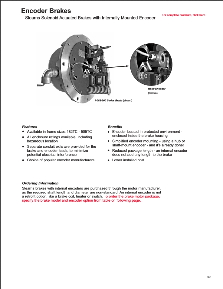
STEARNS Electric Motor Brakes . Stearns offers a comprehensive line of standard and special AC and DC industrial brakes and clutches. With over 100 years of design and manufacturing experience, Stearns has built a solid reputation for quality, commitment to customer satisfaction and superior reliability. We have only listed the most common ... Brake . BE2. Brake voltage [V]/-torque [Nm] 460 AC / 20. Brake torque [lb-in] 177. Brake rectifier . BG1.5. Brake wiring diagram . B100 / 690010106. Motor protection . TF = PTC Temperature sensor. Terminal box . Terminal box lower part made of aluminum with tapped hole 3xNPT 1/2" CT speed range . 300-1800rpm Stearns Brake Wiring Diagram. admin January 13, 2022 Templates No Comments. 21 posts related to Stearns Brake Wiring Diagram. Rzr Brake Light Wiring Diagram. Brake Controller Wiring Diagram Ford. Primus Brake Controller Wiring Diagram. Hopkins Trailer Brake Wiring Diagram. Solenoid style brakes generally react under 40 ms for brakes less than 20 lbft, and 60-80ms for larger brakes. Direct acting brake reaction time is affected by the rectifier choice. Pictures: Power leads at C-face ready for wiring brake internally. Hazardous environment brake wired externally across motor leads in the power box.
Stearns Brake. Failure to comply with these instructions could cause injury to personnel and/or damage to property if the brake is installed or operated incorrectly. For defini-tion of limited warranty/liability, contact Rexnord Industries, LLC, Stearns Division, 5150 S International Drive,Cudahy, WI 53110, (414) 272-1100. Caution 1. Installation and servicing must be made in …
04.04.2020 · Stearns Brake Wiring Diagram Eyelash Me . Stearns Brake 1 048 161 00 Bq Nema 2 208 230 460 3 Phase . Diagram Dc Motor Internal Wiring Diagram Full Version Hd . Bodine Electric N4698 Right Angle Dc Gearmotor 06 Hp 24vdc 63 Rpm . Leeson 5 Hp Brake Motor 3 Phase 1800 Rpm 230 460 V 184tc Frame Tefc 132480 00 . Top 10 Most Popular Motor …
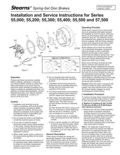
operation of the brake. 8. For proper performance and operation, only genuine Stearns parts should be used for repairs and replacements. 9. After usage, the brake interior will contain burnt and degraded friction material dust. This dust must be removed before servicing or adjusting the brake. DO NOT BLOW OFF DUST using an air hose.
Torqube. Cobra. Browning Syncrogear and Gearmotors. SHUR-STOP BRAKE KITS. Additional Manuals & PDF Files. Varidrive Manual. 1 Frame Varidrive Parts Diagram. 6 Frame Varidrive Parts Diagram. 10 Frame Varidrive Parts Diagram.
tion of the brake. 8. For proper performance and operation, only genuine Stearns parts should be used for repairs and replacements. 9. After usage, the brake interior will con-tain burnt and degraded friction material dust. This dust must be removed before servicing or adjusting the brake. DO NOT BLOW OFF DUST using an air hose.
02.04.2020 · Stearns Brake Wiring Diagram Eyelash Me . Stearns Brake 1 048 161 00 Bq Nema 2 208 230 460 3 Phase . Diagram Dc Motor Internal Wiring Diagram Full Version Hd . Bodine Electric N4698 Right Angle Dc Gearmotor 06 Hp 24vdc 63 Rpm . Leeson 5 Hp Brake Motor 3 Phase 1800 Rpm 230 460 V 184tc Frame Tefc 132480 00 . Top 10 Most Popular Motor …
To help you with the installation and accuracy in wiring our programs, we’ve put a collection of wiring diagrams at your fingertips. LM1-326 Radio Receiver. LM2-Non-Metered AC. LM3-Non-Metered Stored Water. LM4-Non-Metered AC and Stored Water. LM5-Sub Metered 1 Circuit Electric Heat. LM6-Sub Metered 1 Circuit Electric Heat/Stored Water.
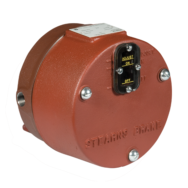
Welcome to Stearns. We're a Wisconsin-based manufacturer that produces a nationally distributed line of spring set motor brakes and brake parts. Get your industrial brake in as little as five days. Enter my Brake Specifications Browse our Digital Catalog Find a Distributor Industrial Electric Brake Products Reliable Motor Brake Parts.
Electric Motor Wire Marking & Connections. For specific Leeson Motor Connections go to their website and input the Leeson catalog # in the "review" box, you will find connection data, dimensions, name plate data, etc. www.leeson.com Single Phase Connections: (Three Phase--see below) Single Voltage:
3 Apr 2009 — ing, or servicing your Stearns Brake. Failure to comply with these ... All wiring and elec- ... dual voltage diagram on solenoid frame.
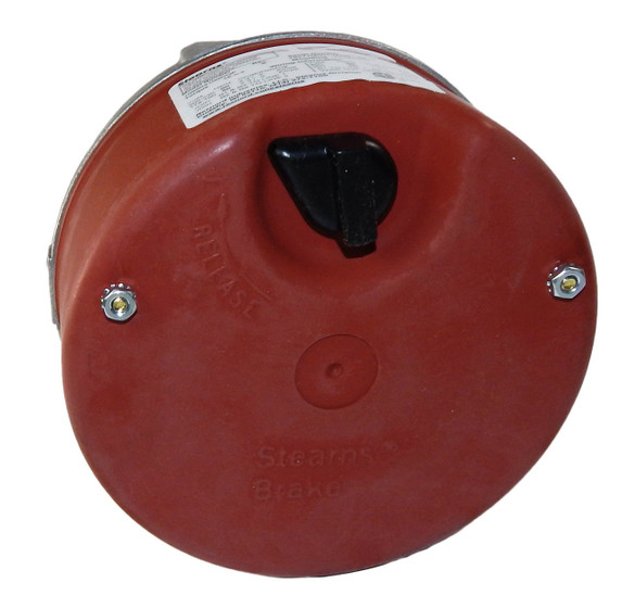
Stearns brake wiring diagram. Stearns offers a comprehensive line of standard and special AC and DC industrial brakes and clutches. With over 100 years of design and manufacturing experience, Stearns has built a solid reputation for quality, commitment to customer satisfaction and superior reliability. See Our Certifications.
RS-1-SH Relay & Controls |1.5 hp - 2 hp Electric Motor Reversing Drum Switch - Position = Maintained
24.01.2019 · Stearns Brake Wiring Diagram . January 24, 2019 1 0 . Wiring instructions for ac voltage coils rexnord industries stearns 1 056 000 table of contents sinpac switches split phase motors series brakes installation and service 87 300 00. Wiring Instructions For Ac Voltage Coils ...
Stearns Brake Wiring Diagram; Newborn Baby Boy Party Invitation Card; 5 Way Round Trailer Wiring Diagram; Wedding Invitation Templates Word Document; Archives ... ford 3000 tractor power steering diagram; 2004 ford e150 brake lines diggram; hot water heater circulating pump diagram;
Stearns Brake Wiring Diagram; Newborn Baby Boy Party Invitation Card; 5 Way Round Trailer Wiring Diagram; Wedding Invitation Templates Word Document; Archives ... ford 3000 tractor power steering diagram; 2004 ford e150 brake lines diggram; hot water heater circulating pump diagram;
Stearns Brakes Stearns Replacement Parts Item Number 3105101000E1 Part Number 3105101000E1 Overview Documents Product Description : Stearns Brakes 3105101000E1 3.35 AAB-S BRAKE, .750 B Learn More Stearns Brakes Stearns Replacement Parts Item Number 330652200E02 Part Number 330652200E02 Overview Documents
Stearns Brake. Failure to comply with these instructions could cause injury to personnel and/or damage to property if the brake is installed or operated incorrectly. For defi- nition of limited warranty/lia-bility, contact Rexnord Industries, LLC, Stearns Division, 5150 S. International Dr., Cudahy, WI 53110, (414) 272-1100. Caution 1. Installation and servicing must be made in …
Brake Mountings. Access a User Manual. Clutches. Access Parts Lists. Discs. Find a Sales Representative or Distributor. Find a Specifications Sheet. Installation. Modifications. Access Wiring Diagrams. Access CAD Drawings. Product Model Interchange Guide. SINPAC | Electric Start Switches. Trouble Shooting . Brake Selection. Order Status. Find Pricing Information. …
Stearns Division,5150 S. International Dr., Cudahy, WI 53110, (414) 272-1100. Caution 1. Installation and servicing must be made in compliance with all local safety codes including Occupational Safety and Health Act (OSHA). All wiring and electrical connections must comply with the National Electric Code (NEC) and local electric codes in effect. 2. Do not operate the …
Stearns Brake. Failure to comply with these instructions could cause injury to personnel and/or damage to property if the brake is installed or operated incorrectly. For definition of limited warranty/liability, contact Rexnord Industries, LLC, Stearns Division, 5150 S. International Dr., Cudahy, Wisconsin 53110, (414) 272-1100. Caution 1. Installation and servicing must be made …
Re: bedroom slide brake issue. Best approach is to bring slide in and then reattach the brake to hold the slide in place. The brake needs a full 12v+ to operate and the wiring from the switch the slide mechanism has a number of connections that can offer resistance. Try the slide after the generator runs a bit to ensure a full 12v.
Stearns Brakes Replacement Parts Item Number 003452400 Part Number 003452400 Overview Documents Product Description : Stearns Brakes 003452400 LOCTITE #242 .5 ML CAPSUL Learn More $5.72 Add to Cart Call for Availability Stearns Brakes Replacement Parts Item Number 10703120 Part Number 10703120 Overview Documents
/Switches%20for%20Capacitor%20Start%20Motors/CV%20Series,%20115v/images/Brochure.jpg)









0 Response to "40 stearns brake wiring diagram"
Post a Comment