41 4-20ma pressure transducer wiring diagram
Figure 1. It is a typical usage of two-wire 4-20mA pressure transmitters for most customers showed in figure 1. After the pressure transmitter is powered on, the loop current is proportional to the pressure to generate a 4-20 mA signal by collecting the pressure. The current flow through the sampling resistor (typical 100 Ω, 250 Ω) which ... WIRING DIAGRAM FOR MODEL CXLdp MODEL CXLdp DIFFERENTIAL PRESSURE TRANSDUCER (4-20mA) INSTALLATION & MAINTENANCE SHEET ZERO SPAN Zero adjust potentiometer Span adjust To troubleshoot or verify performance, it is recommended to pneumatically connect the pressure ports to each other and establish a zero offset reading in the as-installed position.
A typical 4-20mA current loop setup contains 3 things power supply — Most of the devices work at 24V DC but there are other voltage standards available as well4-20mA current loop sensor — this is the device which works as 4-20mA standard. for example, it could be a temperature sensor which gives the temperature value in the form of 4-20mA4 ...
4-20ma pressure transducer wiring diagram
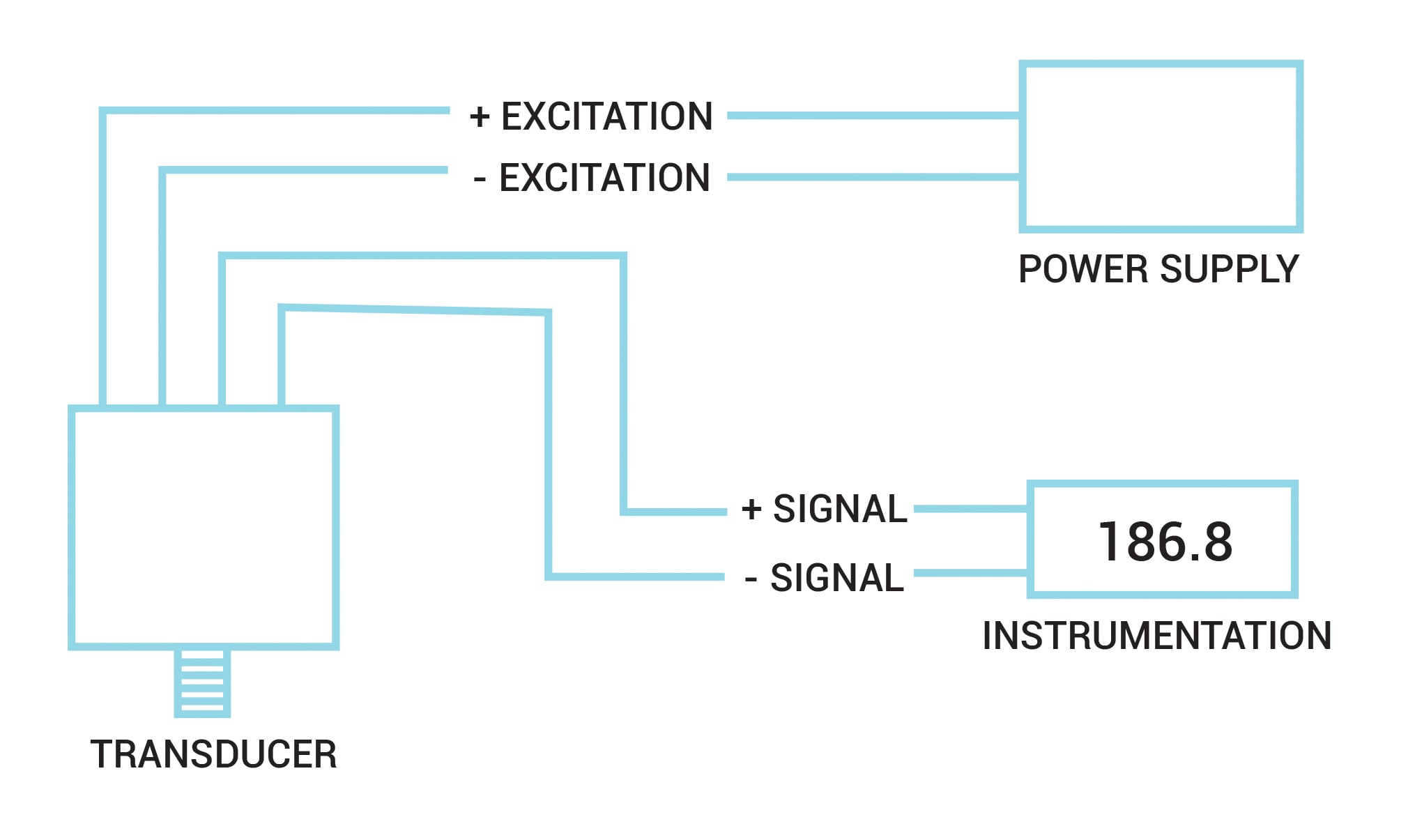
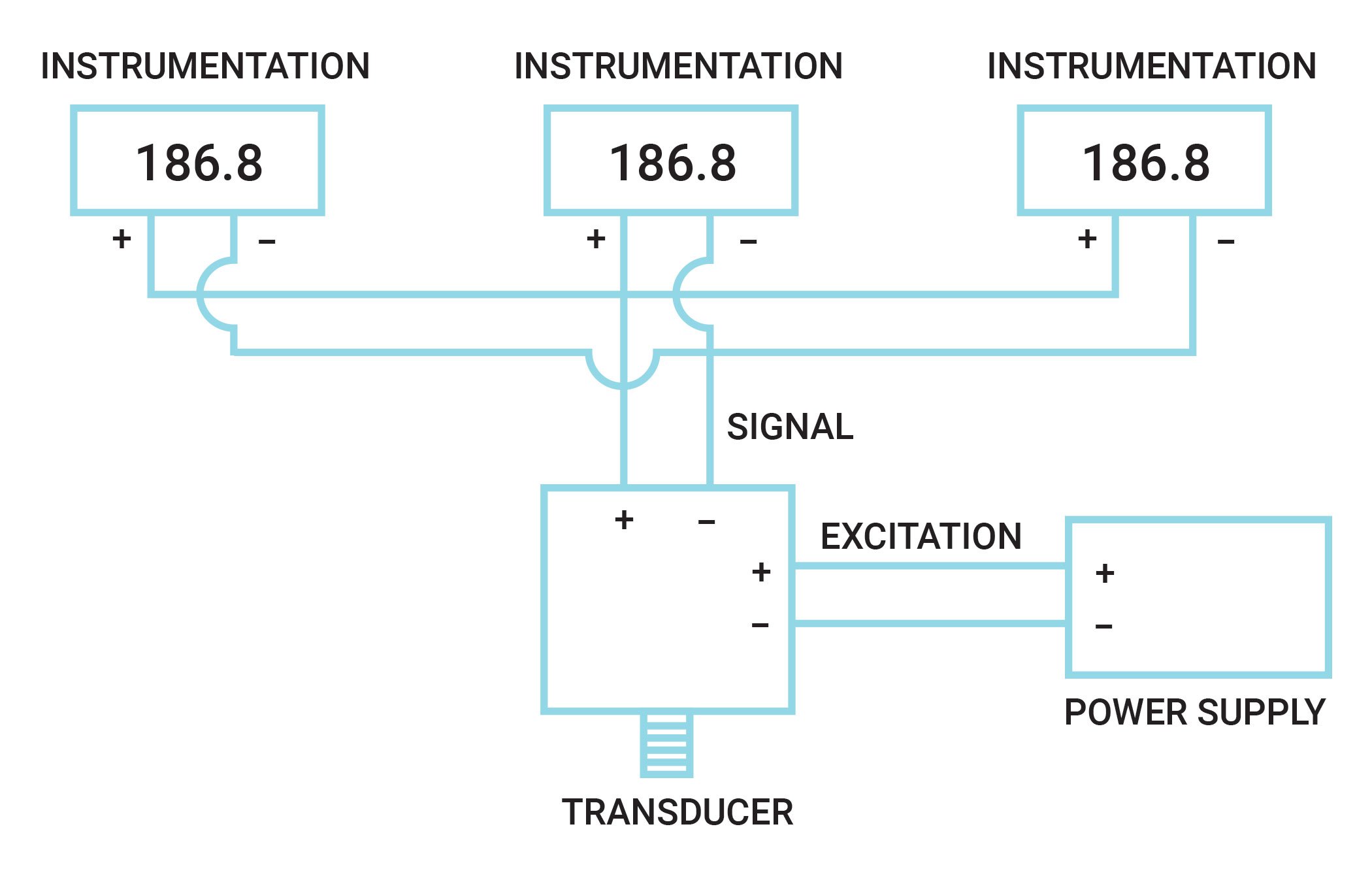
Pressure sensor link, https://www.ato.com/pressure-sensorThe video shows the connection of the 2-wire ATO pressure sensor/transducer. The ATO pressure sensor... We have some sensors in very remote locations with buried junction boxes. How crazy would it be to replace the J thermocouples with PT100 and current transmitters? Type J ext wire is 90.5ohm/100ft but LVT of the same Guage is 24.7ohm/100ft so not so crazy. Would this work as a temporary solution until summer when they can run new conduit or will it overload a PLC card? Figure 1. Typical wiring configuration for millivolt output transducer Figure 3. Typical wiring configuration for current output transducer Figure 4. Multi-instrument 4-20mA current loop (panel meters, chart recorder, computers, etc.) Minimum voltage req'd = (0.20 Amps)(R LINE + R LOAD) + Vs TRANSDUCER Figure 5.
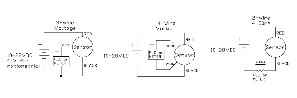
4-20ma pressure transducer wiring diagram. 4-20ma pressure transducer wiring diagram . Why 4-20 mA Standard is so popular ? 4-20 mA Standard 4-20mA has an inherent 'live zero'. Zero engineering units is 4.0mA, not 0.0mA. 0.0mA indicates an open. Categories. 4-20mA Output Signal. 2-wire loop powered. The 4-20mA output signal is an analog output signal commonly used in sensors. It is typically powered by DC voltage ranging from 8-32 VDC, which are widely available commercially. Occasionally, 4-20mA output signals use a three wire configuration (+V, -V, +S), but the vast majority of modern 4-20mA ... 4-20mA (2 wire loop powered)* +Temp -Press +Press -Temp NOTICE FOR HAZARDOUS AREA SENSORS (AST46PT) - Refer to operating instructions for installation information. * For units with loop-powered 4-20mA output, the pressure loop must be powered or the temperature output will not operate. 4 20ma Pressure Transducer Wiring Diagram Sample The best choice is always to use a verified and accurate Pressure Transducer Wiring Diagram that's provided from a trusted source. A good, customary company that has a long track stamp album of providing the most up-to-date wiring diagrams nearby is not hard to find.
ChemE here again with another PLC question. I'm using [this PLC](https://www.rexelusa.com/usr/Root-Category/Control%2C-Automation/Measuring%2C-Monitoring-%26-Logic-Devices/Programmable-Logic-Controllers/PLC%27s---Logic-Controllers/Allen-Bradley-1769-L33ER-Controller%2C-2MB-Memory%2C-No-Embedded-I-O%2C-1769-Power-Supply/p/357022) with the 1769-IF16C AI module (page 30 of the manual). I've replaced an old [3-wire connection flow meter](https://aw-lake.com/product/edge-flow-sensor/) with a new [2-w... My company has a temperature probe (PT100) that outputs a 4-20mA for a data logger but now they want to add a feed back loop into the system with a heat exchanger that needs an input signal of a PT100 directly. Does anyone know of an off the shelf signal transducer from 4-20mA to PT100 signal? From what I've seen so far, I need a low-pass filter but I'm having trouble trying to figure out the exact values I would need for the resistor and capacitor. What would you recommend? Edit: [Here's the datasheet](http://cgproducts.johnsoncontrols.com/met_pdf/216370.pdf). I'm planning to use this for a little marshmallow cannon sort of thing, where I can change the air pressure using wifi or bluetooth. I am having a issue with the wiring of my 03 1.4 polo does anyone know where i can get a wiring diagram?
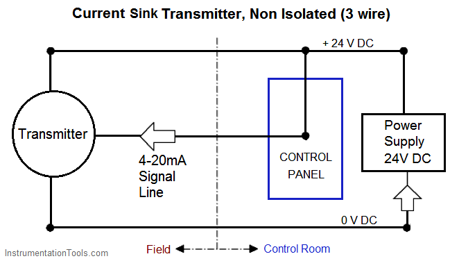
I am trying to read the analog signal from this transducer: https://docs.google.com/viewerng/viewer?url=https://merit.s3.amazonaws.com/catalog/Brochures/400545002-B.pdf From the brief research I've done I think I need to be using an op-amp (LM358 for example) but I am not sure how to wire it and which resistors to use. In this video, we show you how to wire a pressure transducer two ways: 2 wire for current transducers and 3 wire for voltage transducers.To learn more, visit... Hi everyone! Have anyone connected a schneider ATV310 to a pressure transducer to control the pressure of water in a pumping system? I have wired the transducer (2-wire) to the vfd but I have no idea how to configure parameters inside the vfd to control the pump in order to maintain the correct pressure! Any insights? Industrial transmitters are available for monitoring many parameters these including pressure, temperature and flow etc. Gas detectors / transmitters offer 4-20mA outputs, where 4 mA equates to a zero reading and 20 mA equates a full scale reading of the calibrated range.. This signal is sent to a remotely located control panel.
3 Wire
4 20ma Pressure Transducer Wiring Diagram Download. 4 20ma pressure transducer wiring diagram - A Novice s Overview of Circuit Diagrams An initial appearance at a circuit representation could be complicated, but if you can read a subway map, you could check out schematics. The function is the exact same: receiving from point A to direct B.…

Solved: I am having trouble Omega PX4200 Pressure Transducers ...
I am using an omega pressure sensor with 4-20mA output (px215-300GI) along with an external power supply of 12V. I am unsure about which connection in the wiring diagram refers to the (+) terminal on the sensor.
USE OF SUBMERSIBLE PRESSURE TRANSDUCERS IN WATER-RESOURCES ...
The SI-300 4-20mA/Voltage Pressure Transducer, also called pressure transmitter 4-20mA. It is a pressure sensor with 4-20ma/Voltage output. 4-20mA Pressure Transducer can be OEM as differential pressure, explosion-proof, or sanitary, just as you need.Ideal for OEMs, process applications, water processing, and industrial pressure applications.
Pressure Sensor vs Transducer vs Transmitter | TE Connectivity
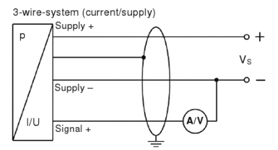
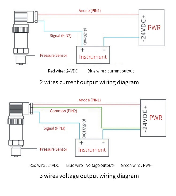
Pressure sensors with a 0.5…4.5V output for industrial 3-wires current loop (4…20mA) applications Nov. 2004 4/9 Analog-Digital Micromechanical Sensor Systems Description of the application Pressure transmitter SM5812's output signal of 0.5V…4.5V is to be converted into an output current signal of 4…20mA as a 3-wire version.
100 Series Current Output Pressure Transmitters On Circle ...
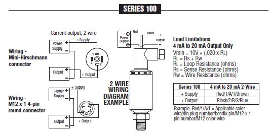
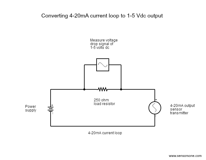
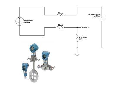
Also most (and yours according to the second datasheet) 4-20ma transmitters utilize only use two wires to the sensor, labled + & -. You have to create a current loop comprising of a voltage source (10V to 30V d.c. (24V d.c. maximum above 110°C)) and a 250 ohm resistor. The wiring would go from negative of the voltage source to resistor, then ...

4 Wire Pressure Transducer Wiring Diagram | Transducer ...
converters (current-to-pressure transducers) are available to convert the 4-20mA control loops to common pneumatic ranges, such as 3-15psi, 1-18psi, 3-27psi, and 6-30psi. In two-wire 4-20mA control loops, we use 2-wire transmitters to convert various process signals representing flow, speed, position, level, temperature,
4 to 20 mA Current Loop Configurations - Application Note - BAPI
I just purchased a 4x12 cabinet that is wired to 16 ohms with 8 ohm speakers. I can find plenty of diagrams that show how to wire it to 8 ohms, but not to 4. Can anyone provide a diagram or advice on how to go about this?

Electrical Connections & Wiring Guide - Dylix Corporation
I have a project that needs to run 8-twisted pair cable (16 wires) to run 8 separate 4-20ma current loop sensors back to a control board. The run is through a steel industrial structure but one that has no electric motors running (only lighting). I know the outside of the 8 twisted pair cable should be shielded, but does each individual pair need to be shielded? I plan to use 22awg wire for our voltage drop requirements. Any advice?

Output Signals - ESI Transducer
While reviewing the wiring diagram on some pressure transmitters (2-wire 4-20mA output, direct wire) I'm about to buy I noticed a slight inconsistency with the wiring in the NI9203 user manual. Here are links to the user manuals for the sensors: Swagelok pressure transducers

Pressure transmitter mounting. Part 2. 4...20 mA electrical connection
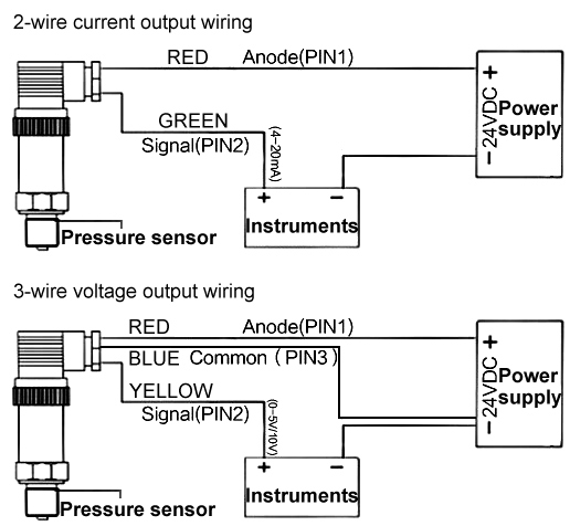
A) If the 4-20mA Input Device includes an Internal Sensor Power Supply and has 2 input connections: Connect Positive (+) Input connection to Positive (+) Pressure Transmitter connection; Connect Negative (-) Input connection to Negative (-) Pressure Transmitter connection; B) If the 4-20mA Input Device requires an External Sensor Power Supply and has 2 input connections:
![Question 3. [15 marks] An analog signal of 4 to 20 mA | Chegg.com](https://media.cheggcdn.com/media/3ec/3ec9d614-8944-471c-b0e4-e5f142cd573b/phpPKFfvs)
Question 3. [15 marks] An analog signal of 4 to 20 mA | Chegg.com
In order to do the transmission of physical signals such as pressure, temperature, flow, and level we need to convert it to an electrical signal and this can be achieved with the help of a transducer.4-20mA is a standard signal which can be used to do this transmission. So these signals would reach the controller of a control system like the ...

What are 2-wire and 4-wire Transmitter Output Loops? - RealPars
Hi, I'm currently tasked with replacing a 4-20mA pressure transducer that looks a lot like one of these: https://www.adminstrumentengineering.com.au/files/product/pdf/Lutron_TR-PS2W.pdf The catch is that we can't get a part identical to the original, and I want to make sure that the replacement has compatible characteristics. For the life of me I can't understand how a 2-wire device can consistently regulate current across a range of input voltages (9-30V) and possibly different loading chara...

Pressure Transducer, Transmitter or Sensor? | The Design ...
Today's electronic process transmitters - pressure, temperature, flow and level are connected in different wire types or configurations. These connection methods are of great concern to the instrument engineer/technician. The 2 - Wire, 3 - Wire and 4 - Wire types are often used to describe the method of connection of electronic transmitters.
4 to 20 mA Current Loop Output Signal
Have any of you guys used 3-wire transmitters with the 5069-IF8? If so, how did you accomplish it?

Differential Pressure Sensors | The Design Engineer's Guide ...
My Project requires me to Sense Pressure though a 9-28VDC, 4-20mA, 2 wire sensor. I have done a lot of readings and I have a few questions. 1. Do I need 24V to work with the sensor ? I have 12v in the PCB I am making and I dunno much about these sensors. can I use 12V ? 2. The sensor is just used to display pressure.
Difference of 4-20 mA in 2-wire & 3-wire technology - WIKA blog
Wiring Diagram Images Detail: Name: 4 20ma pressure transducer wiring diagram - 4 20ma Transmitter Circuit Diagram Best 3 Wire Pressure Transducer Wiring Diagram. File Type: JPG. Source: golfinamigos.com. Size: 101.01 KB. Dimension: 985 x 729.
High Temperature Pressure Sensor for Steam/Fuel Oil | ATO.com
Can someone point me towards the FULL wiring diagram for this?

AST4000 Pressure Sensor Datasheet | Manualzz
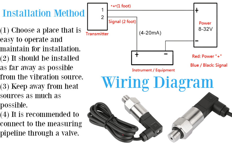
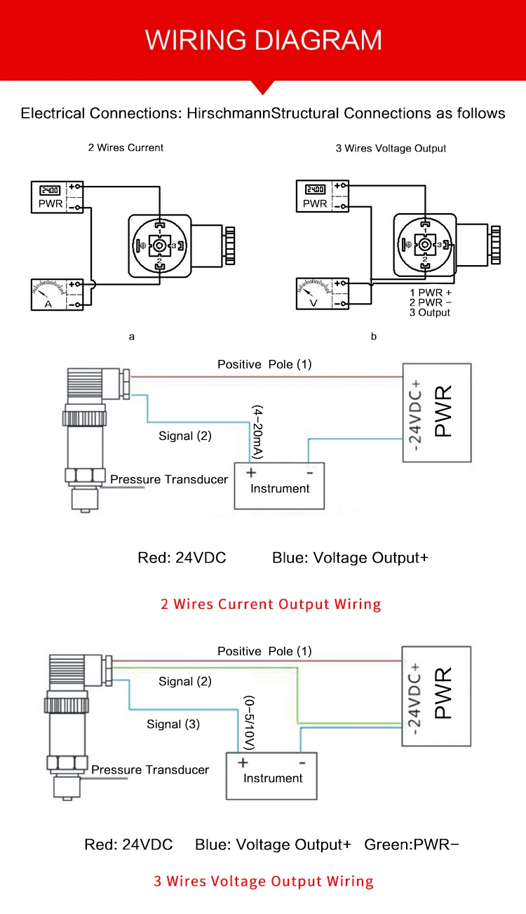
4-20mA Help 2 wire 4-20ma pressure transmitter wiring configuration. The diagram below below shows a simple wiring configuration for current loop pressure transmitter. It is assumed that the measurement device includes a sufficient load resistance for measuring a current loop.

Fst800-1100 Packard Cheap 0545V 4 20mA Small Mems Capacitive ...
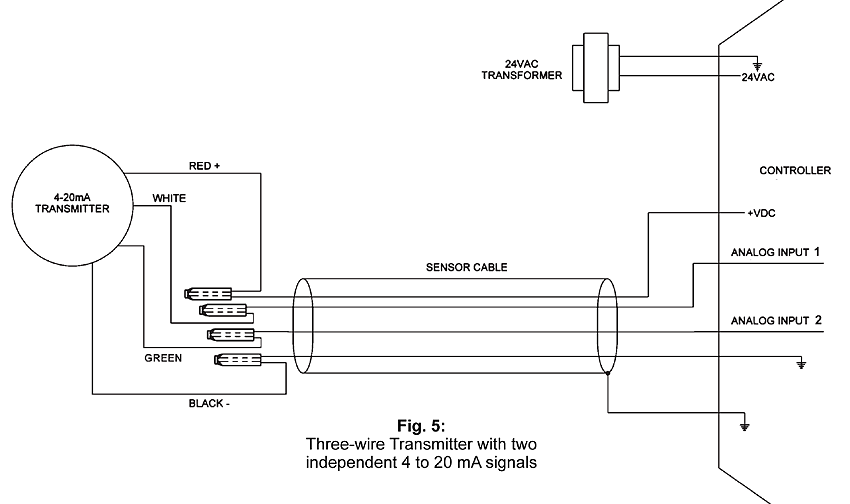
For 4-20mA loops with 2-wire transmitters, common power supply voltages are 36VDC, 24VDC, 15VDC and 12VDC. Current loops using 3-wire transmitters can have either AC or DC power supplies. The most common AC power supply is the 24 VAC control transformer. Be sure to check your transmitter's installation manual for the proper voltage requirements.
Operating Manual
The 4-20 mA current loop is the dominant standard in many industries. It is the simplest option to connect and configure. It uses less wiring and connections than other signals, greatly reducing initial setup costs. Better for traveling long distances, as current does not degrade over long connections like voltage.

4 to 20 mA current loops made easy
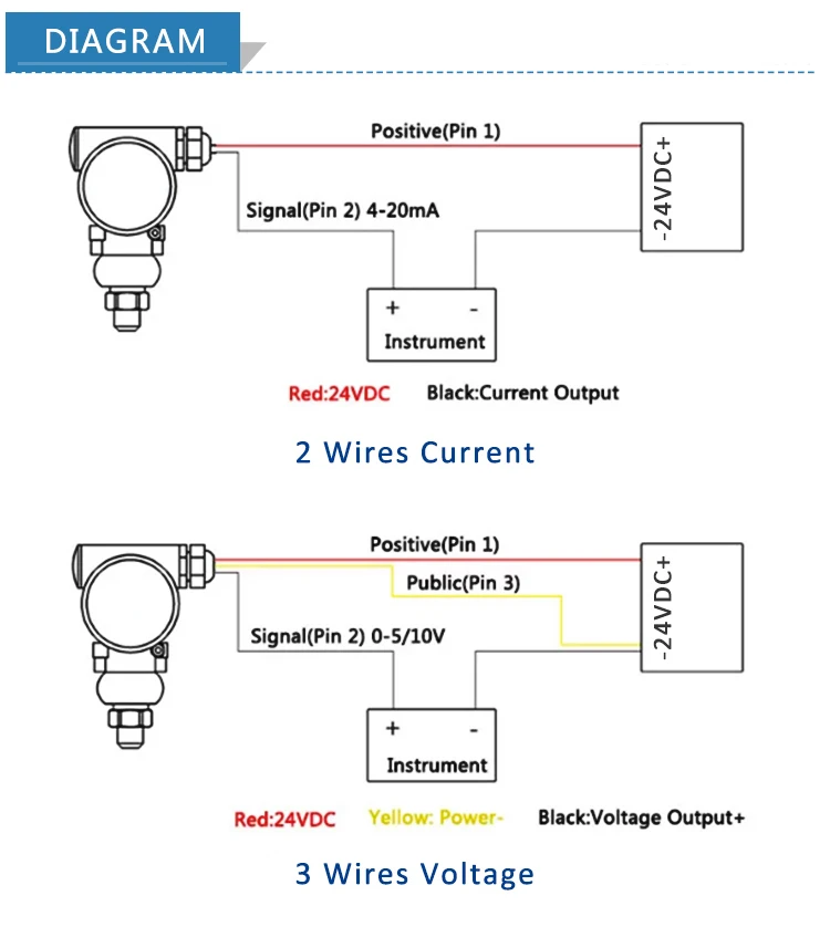
A wiring diagram is a streamlined standard pictorial depiction of an electric circuit. 2 wire pressure transducer wiring diagram 4 20ma transmitter circuit diagram awesome 3 wire pressure transducer wiring diagram. All devices in a 4 20 ma current loop need to be supplied power from somewhere in order to function.
Pressure Transducers |Installation and Wiring Diagrams
I'm currently working on a project where I've developed a sensor system that will monitor depth and temperature variations of a river with 50' max depth and temperature range of roughly 30 F to 80 F. The sensor operates at 3.3 V and draws only a couple mA of current. The issue I'm at now is finding a cost efficient cable system for this. I need a 4 conductor(22-26AWG) cable with sealed connectors that could last upwards of 10 years submerged in fresh water. Any ideas on affordable options(<...
Amazon.com: Psi Pressure Transducer 4-20mA Output G1/4 ...
4 20ma Pressure Transducer Wiring Diagram. Variety of 4 20ma pressure transducer wiring diagram. A wiring diagram is a simplified conventional pictorial representation of an electrical circuit. It shows the parts of the circuit as simplified forms, and also the power and also signal links in between the devices. A wiring diagram typically provides info about…
Pressure Transmitter 10 Bar High Accuracy Pneumatic Water Pressure Sensor For Tank 0-10v Output - Buy Pressure Transmitter,Air Pressure Sensor,Oil ...
I have a project that needs to run a 8-twisted pair cable (16 wires) to run 8 separate 4-20ma current loop sensors back to a control board. The run is through a steel industrial structure but one that has no electric motors running (only lighting). The wire is about 200m long. I know the outside of the 8 twisted pair cable should be shielded, but does each individual pair need to be shielded? I plan to use 22awg wire for our voltage drop requirements. Any advice?
OMEGA ENGINEERING - Pressure Transducers - Installation and Use
Pressure Transducer and Transmitter Wiring Explained. Jan 24, 2022. Pressure Transducer and Transmitter Wiring Explained Learn how to wire different transducers and transmitters to digital and analog PLC input modules. ; In this article, we're going to show you how to wire a few different pressure transducer and transmitter...
4-20ma Air Pressure Transmitter Oil Water Pressure Transducer ...
Figure 1. Typical wiring configuration for millivolt output transducer Figure 3. Typical wiring configuration for current output transducer Figure 4. Multi-instrument 4-20mA current loop (panel meters, chart recorder, computers, etc.) Minimum voltage req'd = (0.20 Amps)(R LINE + R LOAD) + Vs TRANSDUCER Figure 5.

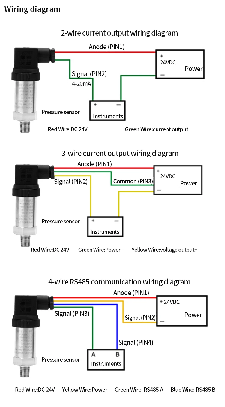
FAQ: How to wire a pressure transducer (2 Wire & 3 Wire)
We have some sensors in very remote locations with buried junction boxes. How crazy would it be to replace the J thermocouples with PT100 and current transmitters? Type J ext wire is 90.5ohm/100ft but LVT of the same Guage is 24.7ohm/100ft so not so crazy. Would this work as a temporary solution until summer when they can run new conduit or will it overload a PLC card?

4 to 20 mA current loops made easy
Pressure sensor link, https://www.ato.com/pressure-sensorThe video shows the connection of the 2-wire ATO pressure sensor/transducer. The ATO pressure sensor...
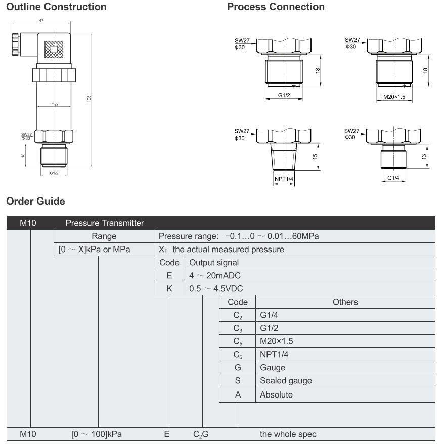
AMO M10 Industrial Pressure Transducer 4-20mA Output (2-wire ...
4 20ma water air gauge pressure transducer 0 50bar|Pressure ...
Smart Water Pressure Sensor 4-20mA Analog Output Digital 2088 ...
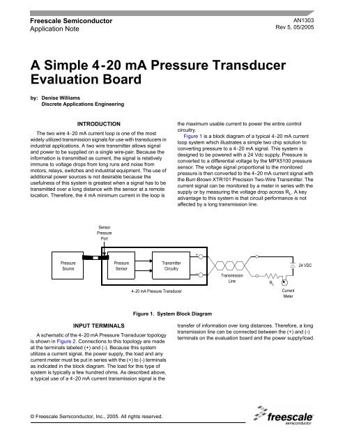
AN1303 A Simple 4-20 mA Pressure Transducer - Freescale ...
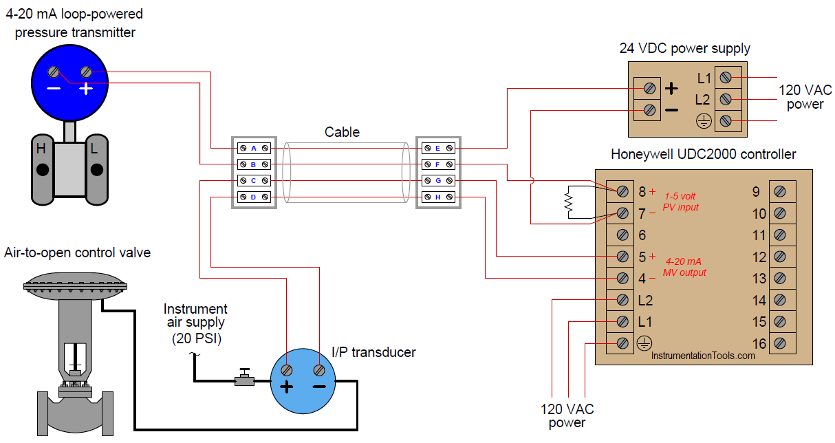
Pressure Control Loop Wiring Connections - Instrumentation Tools

4-20mA Transmitter Test Board Project - Circuit Cellar
How to Measure 4 to 20mA Signal in a Pressure Transmitter

How can I connect YGX-PTS802 differential pressure ...

4-20mA Transmitter Test Board Project - Circuit Cellar

What are 2-Wire and 4-Wire Transmitter Output Loops?
4-20 mA Transmitter Wiring Types : 2-Wire, 3-Wire, 4-Wire
Pressure Transducers |Installation and Wiring Diagrams

4 - 20mA Transmitter Wiring Types: 2 -Wire, 3 - Wire & 4 ...
0 Response to "41 4-20ma pressure transducer wiring diagram"
Post a Comment