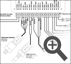
42 dakota digital speedometer wiring diagram
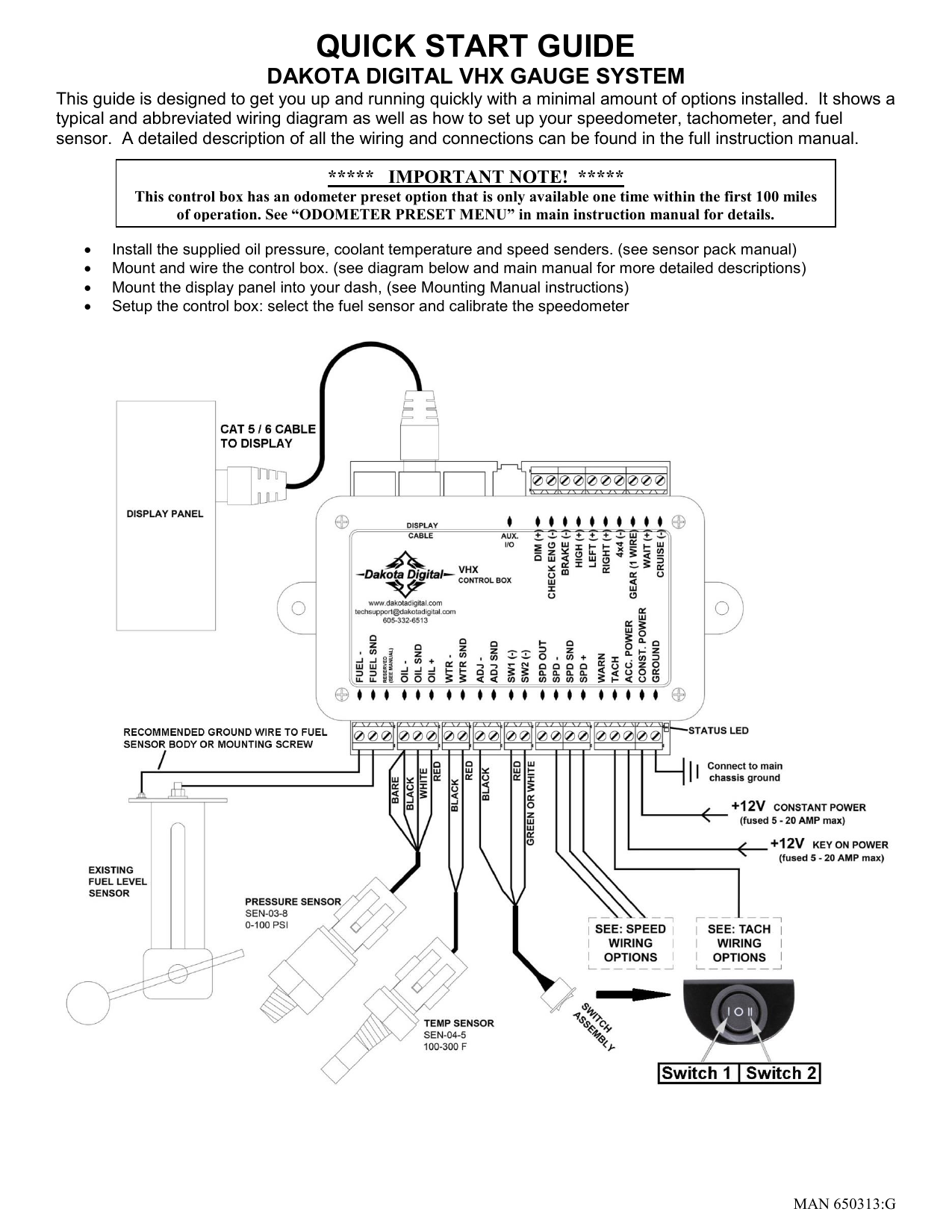
Classic Instruments Wiring Diagram - The Wiring Classic Instruments Wiring Diagram. January 15, 2022. January 15, 2022. 2 5/8" Clock Installation Guide . Smiths Classic digital 100mm (4in) or 80mm dashboard fit 130mph speedo, odo or trip readout, on board "drive-to-set" programming, full range of matching dashboard instruments to return any classic or kit-car dashboard to pristine condition. QUICK START GUIDE - Dakota Digital DAKOTA DIGITAL VHX GAUGE SYSTEM This guide is designed to get you up and running quickly with a minimal amount of options installed. It shows a typical and abbreviated wiring diagram as well as how to set up your speedometer, tachometer, and fuel sensor. A detailed description of all the wiring and connections can be found in the full ...
97 4runner wiring diagram | NC4x4 Jan 9, 2021. #1. Anybody have a wiring diagram for a 97 4runner. I'm wanting to install a dakota digital speedometer calibrator and I have to splice into the wire between the abs module and cluster. I found a write up saying it was a gray-blue wire and just want to confirm before I cut the factory harness. 1997 Peterbilt 379 redneck motorhome.
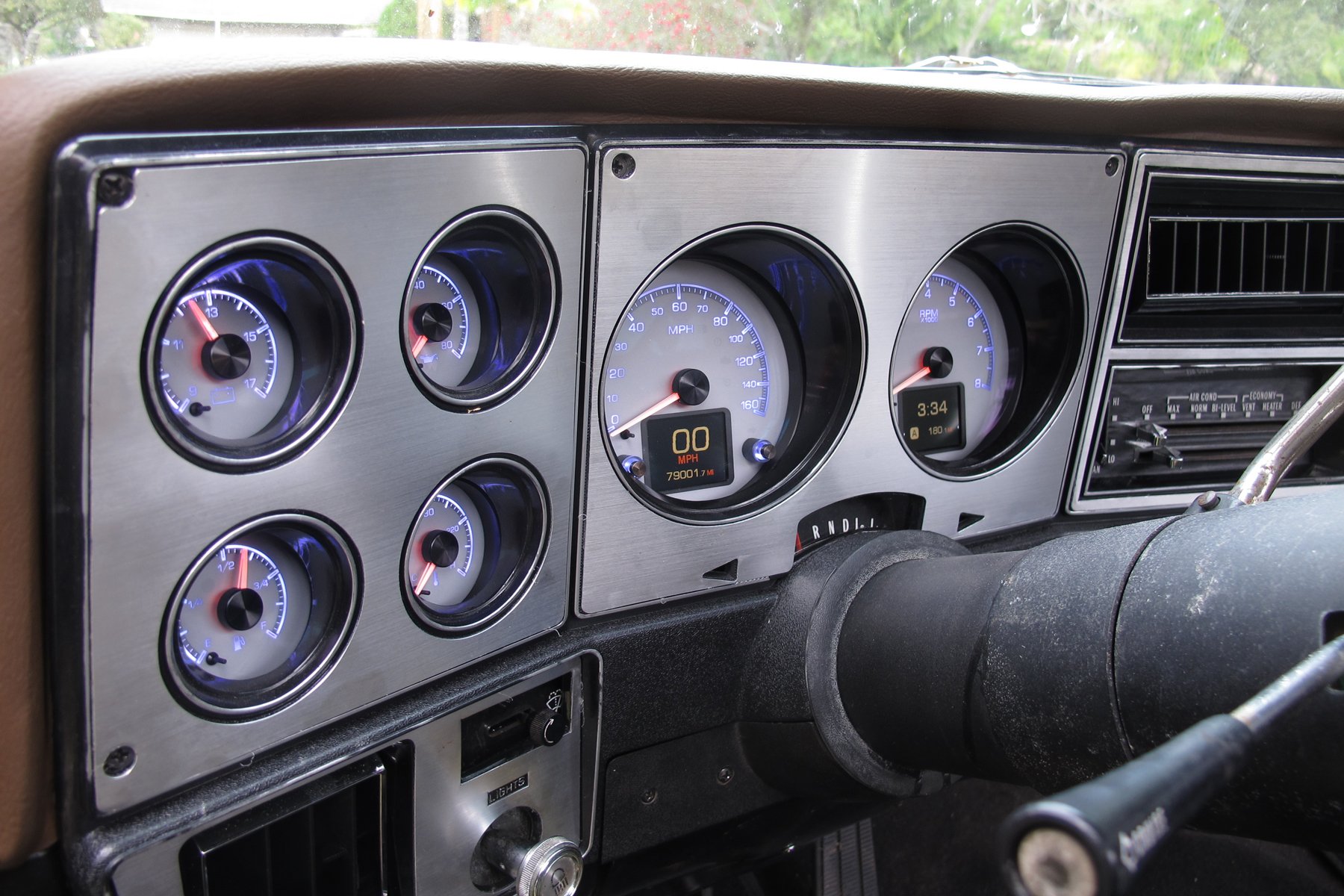
Dakota digital speedometer wiring diagram
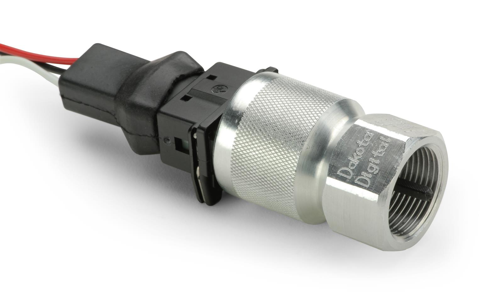
How to Install the Dakota Digital Dash System - 1967 Chevelle Jeff's 1967 Chevelle project undergoes prep for a Dakota Digital Dash System. Keep a factory style dash with this wide sweep speedometer. Learn how to mount and wire modules for the gauge system, gear shift indicator, GPS speedo sender and auxiliary. PDF ECD-100 ELECTRONIC CABLE DRIVE - Summit Racing Equipment The Dakota Digital ECD-100 is designed operate a cable-driven speedometer from a transmission or ECM electric speed signal. Cables are available for GM thread-on (5/8" thread), GM clip-on, or Ford clip-on. The supplied cable threads on to one end of the ECD-100 and the wiring harness exits on the other end. Dakota Digital - Digital Instrumentation and Accessories Dakota Digital continues to increase our rate of manufacturing to meet this exceptional demand. As a result, this is a great opportunity to do business with your choice of stocking Dakota Digital dealers. We thank you for your understanding and support through this!
Dakota digital speedometer wiring diagram. Alfa Milano Registry - Speedo Fix Using Dakota Digital SGI-5 Doing so causes the speedometer to be off by 15% or so so I've been meaning to install the Dakota Digital SGI-5 box that I bought a while ago to fix it but didn't get around to it until today. The install is quite simple but can be a little confusing which wires to hook up and which dip switch settings to set and questions about this get asked ... Dolphin Electronic Speedometer Wiring Diagram - U Wiring That means this GPS module should work on Omega Autometer Dolphin Classic Instruments and Dakota Digital gauges. And today this is the first picture wiring diagram for dolphin gauges. Gps Speedometer Wiring Diagram Vdo Wiring Diagram Free Sample intended for Speedometer Wiring Diagram image size 694 X 671 px. PDF QUICK START GUIDE - Dakota Digital DAKOTA DIGITAL HDX INSTRUMENT SYSTEM This guide is designed to get you up and running quickly with a minimal amount of options installed. It shows a typical and abbreviated wiring diagram as well as how to set up your speedometer, tachometer, and fuel sensor. A detailed description of all the wiring and connections can be found in the full ... Digital Speedometer Installation | V-Twin Forum 5 Posts. Discussion Starter · #1 · Oct 3, 2009. I have a custom chopper with a 110 RevTech Evo style engine. It has a speedo/tach digital gauge. I haven't figured out the speedo part, so decided to install a rocker box speedo/oil pressure gauge. My problem is that the install for the speedometer references one lead wire should go to the ...
PDF Quick Start Guide Dakota Digital Vfd Series Iii Gauge ... DAKOTA DIGITAL VFD SERIES III GAUGE SYSTEM This guide is designed to get you up and running quickly with the minimal amount of options installed. It shows a typical and abbreviated wiring diagram as well as how to set up your speedometer, tachometer, and fuel sensor. A detailed description of all the wiring and connections can be found in the ... Dakota digital speedo problem - Page 3 - Club Chopper Dakota Digital is a USA company with a proud heritage of Made in USA. Shop Tour I work at a manufacturing company located in the USA (well until mid next year that is when our factory will be shut down after transferring the product manufacturing to Malaysia and I will have to find a new job - being layed off is no fun) and while we pride ourselves on the quality of instrumentation we supply ... MODELS VFD3 & RET - Dakota Digital connect it to the speed terminal. You may have to consult a vehicle service manual or wiring diagram to determine wire color and location. This system can accept 4000 ppm – 128000 ppm speed signals. The sensor that Dakota Digital provides is an 8000 ppm type. The speedometer is fully adjustable and calibration is discussed in a later section. Bigdog speedometer wiring - Big Dog Motorcycles Forum Feb 24, 2018. #2. The hly 5000x Dakota digital only had a 5 wire harness and a 3 wire harness but when I opened it up the speed side of the harness was missing my question is I can get one $15 from Dakota digital will big dogs speed sensor work with there cause then I'll have 11 on Dakota and 11 from old wiring to connect.
Dakota Digital VHX Gauge Install And Review The oil sending unit, temperature sending unit, and speedometer sending unit. There was even adapters in the box to make sure that no matter what engine was under the hood, the sending units would fit. Dakota Digital even includes the wiring needed to go from the sending unit to the computer as well - one less thing we would have to buy. Speed Sensor Setup - Tremec T56 & Dakota Digital Hello, can you please help me with the wiring, and the setup for the speed sensor input? My transmission is a T56 Magnum, Dakota Digital speedometer & Dominator EFI. How would you prefer to put this together? I have to use the speed sensor in the transmission for both, the speedometer and speed input on the Dominator ECU. Thank you. Dakota Digital Wiring Diagram - BIXIN1303 Jul 26, 2020 · Dakota Digital Wiring Diagram picture posted and uploaded by Admin that kept inside our collection. Dakota Digital Speedometer Wiring Diagram. Dakota Digital Wiring Diagram have an image from the other. Dakota Digital Wiring Diagram It also will feature a picture of a kind that might be observed in the gallery of Dakota Digital Wiring Diagram ... PDF Quick Start Guide for Your Digital Gauge System DAKOTA DIGITAL VHX GAUGE SYSTEM This guide is designed to get you up and running quickly with the minimal amount of options installed. It shows a typical and abbreviated wiring diagram as well as how to set up your speedometer, tachometer, and fuel sensor. A detailed description of all the wiring and connections can be found in the full ...
Quick Start Guide Dakota Digital Rtx Instrument System ... DAKOTA DIGITAL RTX INSTRUMENT SYSTEM This guide is designed to get you up and running quickly with the minimal amount of options installed. It shows a typical and abbreviated wiring diagram as well as how to set up your speedometer, tachometer, and fuel sensor. A detailed description of all the wiring and connections can be found in the full ...
PDF Installation Instructions Digital Speedometer DIGITAL SPEEDOMETER Installation Tips 1. A 12 V power source MUST be used to power this speedometer. A 12V motorcycle battery is a good alternative for cars without batteries. A battery with minimum 5 amp hour rating is recommended. 2. Wherever possible, solder wire connections and avoid crimp-type connectors.
Dakota Digital Speedometer Wiring Diagram Collection Dakota Digital Speedometer Wiring Diagram Source: Read cabling diagrams from negative to positive and redraw the routine being a straight range. All circuits are the same ~ voltage, ground, individual component, and buttons.
Wiring the control box into the vehicle - Dakota Digital Thank you for purchasing a VHX system from DAKOTA DIGITAL. VHX is a loose acronym for Vehicle Hybrid Instrument Systems. Representing the latest electronic dashboard technology for the street rodder, car, and truck enthusiast alike, the VHX system combines modern digital electronics with a traditional look to give the driver up-to-date and accurate
Terminator to Dakota Digital VHX gauges using BIM-01-2-HLLY Terminator to Dakota Digital VHX gauges using BIM-01-2-HLLY. I've searched and found a few threads, but not one that answers my question. I'm using the BIM-01-2-HLLY to communicate between the Terminator ECU and the gauges. I can get either the 3.5" touchscreen to work or the dash.
2000 Dodge Dakota Wiring Diagram - Wirings Diagram 2000 Dodge Dakota Wiring Diagram - 2000 dodge dakota dash wiring diagram, 2000 dodge dakota headlight wiring diagram, 2000 dodge dakota ignition wiring diagram, Every electrical arrangement is made up of various distinct parts. Each part should be set and linked to other parts in particular manner. If not, the arrangement won't work as it ought to be.
Dakota Digital Installation | Chevy Nova Forum Most other wiring that plugs into processor will come from the oil pressure, water temp sensors & harnesses both supplied with Dakota Digital kit. I THINK the current fuel gauge sensor will work with Dakota cluster and also the current speedometer senso r from my 2004 Tremec 3650 transmission.
Dakota Digital Speedometer Wiring Diagram Apr 12, 2018 · Dakota Digital MCL Series Speedometer So before we cut, spliced, and soldered, we downloaded the OEM wiring diagram for this. diagram to determine wire color and location. This system can cause your odometer mileage to increase very rapidly if the speedometer is reading too fast.The oil sending unit, temperature sending unit, and speedometer ...
Dakota Digital - Digital Instrumentation and Accessories Dakota Digital continues to increase our rate of manufacturing to meet this exceptional demand. As a result, this is a great opportunity to do business with your choice of stocking Dakota Digital dealers. We thank you for your understanding and support through this!
PDF ECD-100 ELECTRONIC CABLE DRIVE - Summit Racing Equipment The Dakota Digital ECD-100 is designed operate a cable-driven speedometer from a transmission or ECM electric speed signal. Cables are available for GM thread-on (5/8" thread), GM clip-on, or Ford clip-on. The supplied cable threads on to one end of the ECD-100 and the wiring harness exits on the other end.
How to Install the Dakota Digital Dash System - 1967 Chevelle Jeff's 1967 Chevelle project undergoes prep for a Dakota Digital Dash System. Keep a factory style dash with this wide sweep speedometer. Learn how to mount and wire modules for the gauge system, gear shift indicator, GPS speedo sender and auxiliary.


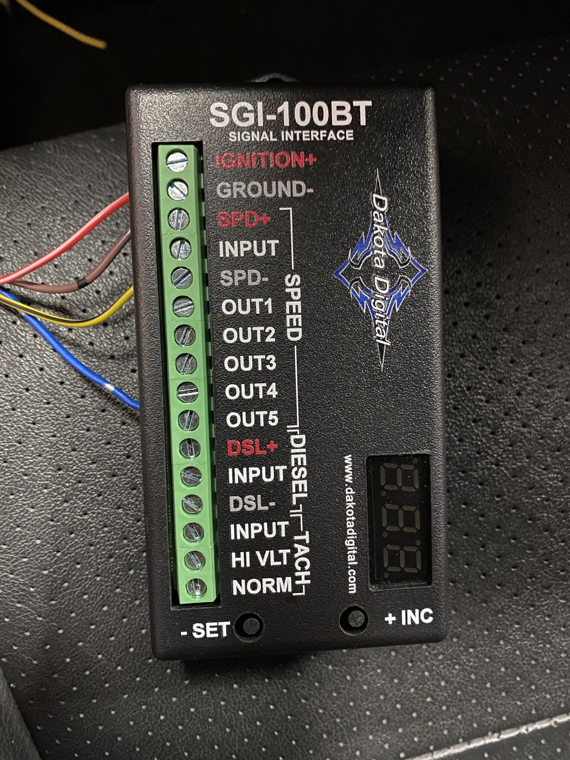
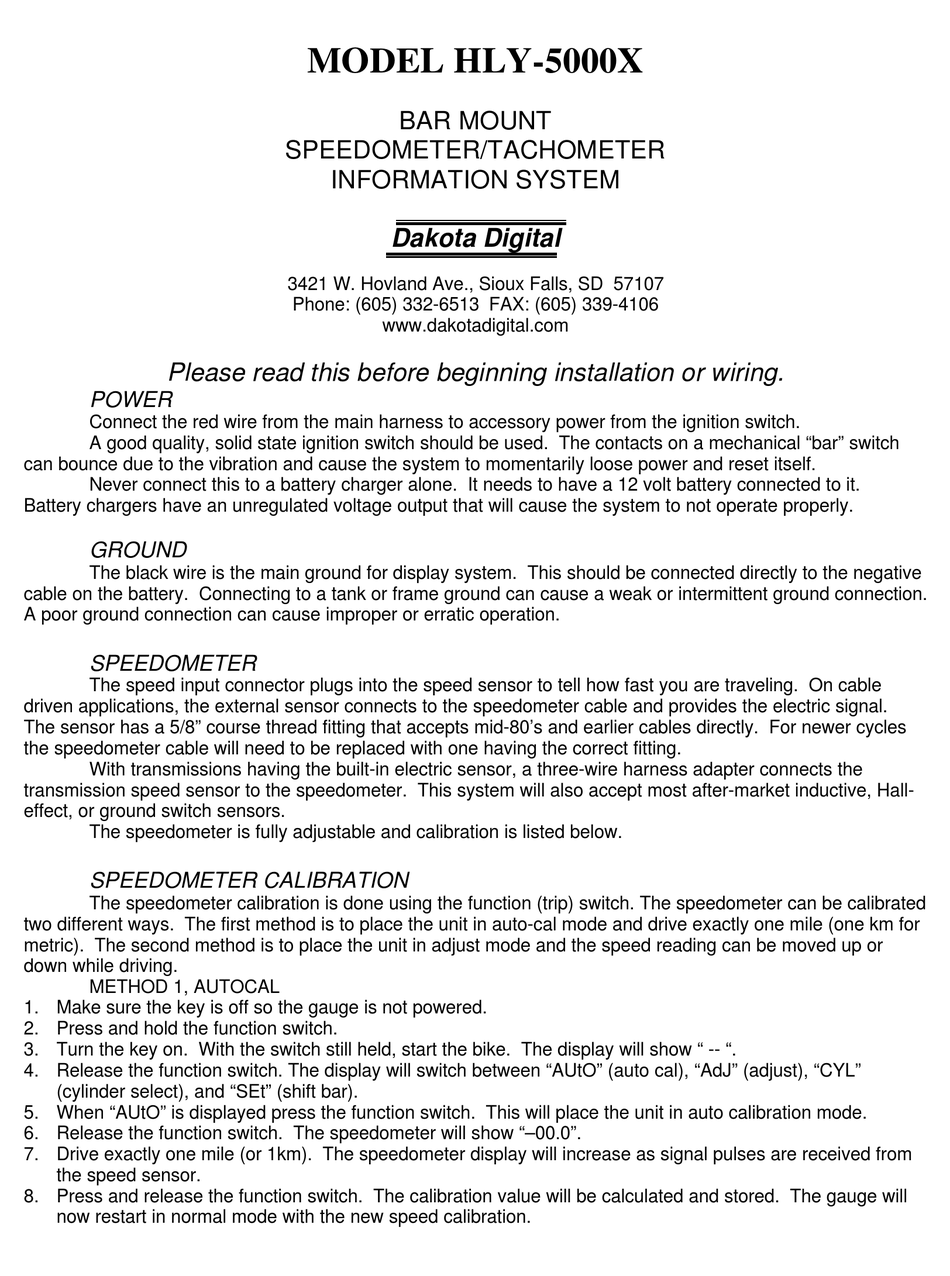



![HOW TO] 240sx speedo wiring Dakota Digital SGI-5E - LS1TECH ...](https://cimg4.ibsrv.net/gimg/ls1tech.com-vbulletin/793x926/98_240sx_gauges_58765adaf20025184460caa8b8d122f31b2ae5d9.jpg)

![HOW TO] 240sx speedo wiring Dakota Digital SGI-5E - LS1TECH ...](https://cimg9.ibsrv.net/gimg/ls1tech.com-vbulletin/870x785/97_98_240sx_cluster_4bd0ca436c2c6104af98b7088c9bb982f5c38b62.jpg)


0 Response to "42 dakota digital speedometer wiring diagram"
Post a Comment