42 Pulley System Free Body Diagram
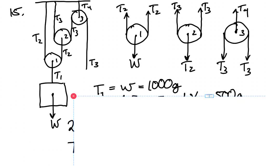
PDF Mechanical Advantage with Pulleys - LEAPS Purpose: Assemble a pulley system to create a mechanical advantage. Draw free body diagrams and apply Newton's Law to accelerating systems. Materials: Assorted pulleys, neon-yellow string, accumulated physics expertise Procedure: 1. Assemble the following pulley system 1 2. Draw the free body diagrams for both M 1 and the bottom pulley in ... (a) Draw a free body diagram for each pulley A mass M is held in place by an applied force F and a pulley system as shown in figure. The pulleys are massless and frictionless. (a) Draw a free body diagram for each pulley (b) Find tension in each section of rope T 1 , T 2 , T 3 , T 4 (c) Find the magnitude of T 1
Tension, String, Forces Problems with Solutions Several problems with solutions and detailed explanations on systems with strings, pulleys and inclined planes are presented. Free body diagrams of forces, forces expressed by their components and Newton's laws are used to solve these problems. Problems involving forces of friction and tension of strings and ropes are also included.. Problem 1
Pulley system free body diagram
newtonian mechanics - Free body diagram of pulley - Physics ... Feb 26, 2016 · Is there any difference between the free body diagram of fixed pulley and movable pulley? Not particularly. The main thing is that you can assume the fixed pulley isn't accelerating, so all forces on it must sum to zero. A movable pulley may or may not be accelerating. is it true that fixed pulley has T1 and T2, but movable has T2 on both sides ... PDF 5-4 A System of Two Objects and a Pulley - WebAssign system of two objects and a pulley. Figure 5.7: Free-body diagrams if there is no friction. (a) The free-body diagram of the red box. (b) An appropriate coordinate system for the red box. (c) The free-body diagram of the red box, with force components aligned with the coordinate system. (d) and (e), a free-body diagram and coordinate system for ... PDF Physics Kinematics, Projectile Motion, Free-Body Diagrams ... pulley. Then they push safe out of the window. What is the safe's speed when it hits the truck? What is the force exerted on the truck by the safe? µ=.5 Rotational Motion 1. Draw a diagram of the object or objects that will be the system to be studied. 2. Draw a Free-body diagram for the object under consideration. 3.
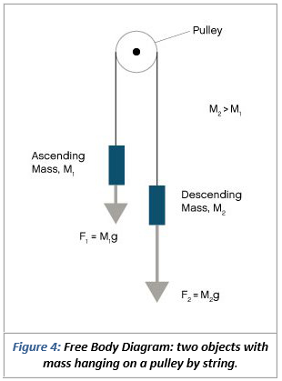
Pulley system free body diagram. Free Body Diagram: Definition, Purpose, Examples, Steps ... Free-Body Diagram allows students to clearly visualize a particular problem in its entirety or closely analyze a particular portion of a more complex problem. So basically, FBD is a very useful aid to visualize and solve engineering problems. Note that, for solving a complex problem, a series of free body diagrams may be required. PDF Modeling Mechanical Systems - California State University ... • Establish inertial coordinate system • Identify and isolate discrete system elements (springs, dampers, masses) • Determine the minimum number of variables needed to uniquely define the configuration of system (subtract constraints from number of equations) • Free body diagram for each element Pulley Problems and Constraint Equation | Physics Pulley ... Now, from the Free Body Diagram (FBD): ... The above technique can be used in almost all possible pulley system consisting of fixed pulleys or movable pulleys. Stay tuned with BYJU'S to learn more about the laws of motion. More Pulley Problem Videos. Pulley Systems. PDF 7. Newton's 2nd Law in More Complicated Problems and Friction 2nd law applies to a system of two connected masses. It is not a practical machine. Suppose two different masses M 1 and M 2 are attached to a rope which is placed over a pulley as indicated in the diagram below. There are TWO free-body diagrams since there are two masses in this problem. M 1 M 2 Pulley X Y W 1 T 1 W 2 T 2 Free-Body Diagram for ...
Solved C. Torque and angular acceleration. 1. Draw an ... Transcribed image text: C. Torque and angular acceleration. 1. Draw an extended free body diagram for the pulley and pulley AT hanger system (see the diagrams to the right) Remembering that the falling weight is undergoing acceleration (but not at gl, the linear acceleration is related to the angulor acceleration by and torque is related to force by TF, we have. hanger pulley mass hanger: mg-T ... Pulley system free body diagram - YouTube About Press Copyright Contact us Creators Advertise Developers Terms Privacy Policy & Safety How YouTube works Test new features Press Copyright Contact us Creators ... 2.972 How an Elevator Works - Massachusetts Institute of ... Free body diagram of the pulley system: The following analysis has been done for steady state (no acceleration )operation. The force on the driving pulley is equal to the difference of the two exerted tensions on each side. On one side, this force is equal to W e and on the other side, it is W c. Two-Body Problems - Physics Classroom The free-body diagrams for each individual mass are shown below. Each object is experiencing a downward force of gravity - calculated as m 1 •g and m 2 •g respectively. Each object is also experiencing an upward tension force that pulls the two objects towards each other.
What is Free Body Diagram in Physics - Definition, Purpose ... Assuming no friction in the pulley system. Free body diagram examples calculation equations Find out the value of force in newton which should be applied to the rope for moving the metal block up the incline. Process to Draw Free Body Diagram Step 1: Draw the object Draw the object on which the force is applied without any vectors or arrows. Free Body Diagram (how do you make free body ... - YouTube Making accurate free body diagrams for a system of blocks connected by string and pulleys is an important step towards writing the correct equations of motio... Pulleys - atozwiki.com A pulley may have a groove or grooves between flanges around its circumference to locate the cable or belt. The drive element of a pulley system can be a rope, cable, belt, or chain. The earliest evidence of pulleys dates back to Ancient Egypt in the Twelfth Dynasty (1991-1802 BCE) and Mesopotamia in the early 2nd millennium BCE. PDF Physics 20 Lesson 18 Pulleys and Systems masses that are connected and accelerating together. Using the pulley system illustrated to the right below as an example, the basic method for discussed. As in Lessons 15, 16 and 17, the basic method is to draw a free body diagram of the forces involved, write an expression for the net force, and then solve for the acceleration. In a pulley ...
Solved Use the free body diagram of the pulley (Figure 4) to ...
PDF 4.3. Tension and Pulleys Pulleys: Demonstration 1. How might a pulley change tension? 2. What would the free-body diagram of the balance of forces be for a rope and a pulley: a. For the rope turned 90 degrees? b. For the rope turned 180 degrees? 3. Experiment!

Statics eBook: Equilibrium & Free Body Diagrams
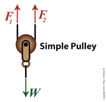
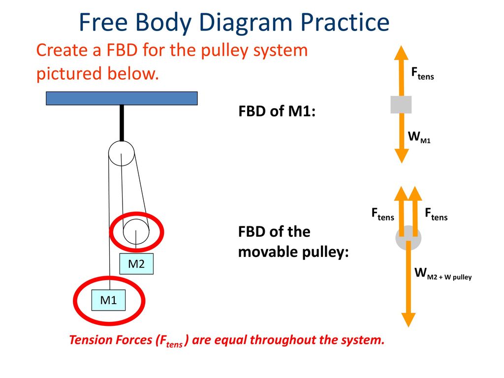
PDF Activity 2.1.3 Free Body Diagrams Free Body Diagram Practice M1 M2 FBD of Mass 1: F T FBD of the movable pulley: W 1 W 2 + W pulley F T F T Tension Forces (F T ) are equal throughout the system. Create a FBD for the pulley system pictured below.
free body diagram for pulley
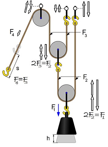
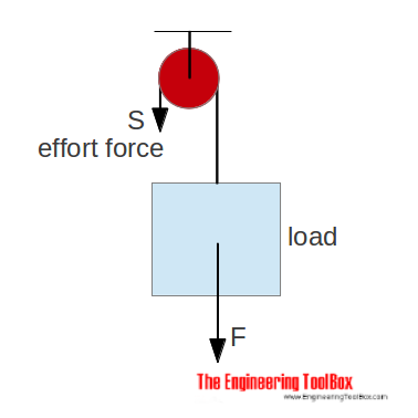
Basic Mechanics - Rice University From the perspective of a free-body diagram the compound pulley system could be replaced by tying two ropes to the load and pulling up on each with a force equal to the effort. The disadvantages of pulleys, in contrast to machines that use rigid objects to transfer force, are slipping and stretching.

Solved DRAW FREE BODY DIAGRAMS FOR ALL OBJECTS IN THE | Chegg.com
Pulley Free Body Diagram - Physics Forums fbd free body diagram pulley system statics Sep 20, 2015 #1 Alison A. 86 2 Homework Statement A collar with a pulley slides on a frictionless vertical bar GH. A string A B C D is wrapped around, where portion AB of the string is horizontal. A spring with 2.5 lb/in. stiffness is placed between the collar and point H.
File:Power Pulley FBD.jpg - Wikiversity
Pulley in Physics - pulley tension problems with solution ... figure 1 - pulley setup We have to draw one free-body diagram (FBD) for the hanging cylinder and another for the cart. 1. Each subject is represented by a dot (labeled with the mass) in Figures 2 and 3. - Figure 2 shows the FBD of the cart. - Figure 3 represents the FBD of the cylinder. 2. Forces are drawn and labeled on each object.

Solved C. Torque and angular acceleration. 1. Draw an | Chegg.com
Finding the period of pulley system | Physics Forums Gold Member. 37,369. 7,359. songoku said: Change in total distance from the top of spring 2, round both pulleys and down to the mass. = change in the section from the top of spring 2, to pulley B + change in the section from pulley B to pulley A + change in the section from pulley A down to the mass.

Problem: Two masses on a pulley | Phyley
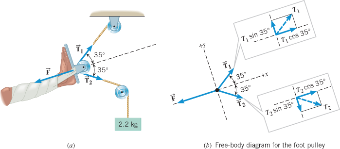
Free Body Diagram -Study Material for IIT JEE - askIITians We can draw the free body diagram of bob at a as shown in figure 1.43. The force acting on the bob is it's weight mg and tension T of the string. Tenstion T is resolved in two components T cos θ and T sin θ as shown in figure 1.43. we can write the equation of motion. T cos θ = mg T sin θ = mv2/r.

AP Physics Resources: Free Body Diagrams for AP Physics B and C
PDF Example 8.9 Pulleys and Ropes Constraint Conditions Because the string is assumed to be massless and the pulley is assumed to be massless and frictionless, the tension T A in the string is uniform and equal in magnitude to the pulling force of the string on the block. The free-body diagram on block 1 is shown in Figure 8.41(a). 1 2 . 3 P (a) (b) (c) (d) ˆ j T A ,1 B m 1 g ,2 m 2 g T B

A5_S18 - Physics 5 Labs
PDF ENGR-1100 Introduction to Engineering Analysis FREE-BODY DIAGRAMS (Section 5.2) 2. Show all the external forces and couple moments. These typically include: a) applied loads, b) support reactions, and, c) the weight of the body. Idealized model Free-body diagram (FBD) 1. Draw an outlined shape. Imagine the body to be isolated or cut "free" from its constraints and draw its outlined shape.
Why is the upward force acting on a pulley which is hanging ...
Solved C. Torque and angular acceleration. 1. Draw an ... 1. Draw an extended free body diagram for the pulley and pulley AT hanger system (see the diagrams to the right) acceleration (but not at g), the linear acceleration is related to the angular acceleration byand torque is related to force by tr', we have. mass hanger 2. Remembering that the falling weight is undergoing

Blocks and Pulley Systems and Tension Force - Example 2 ...
Free Body Diagrams, Tutorials with Examples and Explanations The free body diagram helps you understand and solve static and dynamic problem involving forces. It is a diagram including all forces acting on a given object without the other object in the system. You need to first understand all the forces acting on the object and then represent these force by arrows in the direction of the force to be drawn.
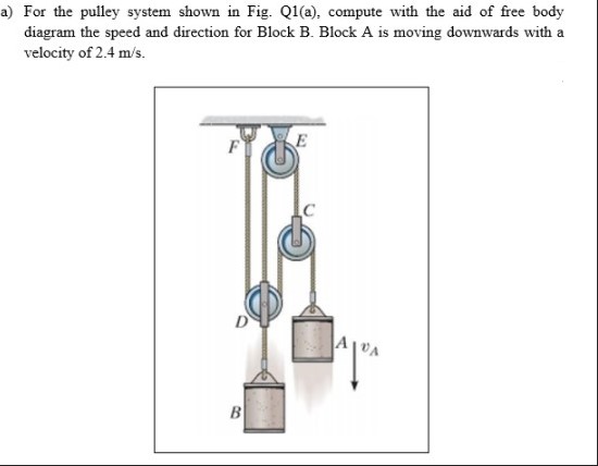
Answered: a) For the pulley system shown in Fig.… | bartleby
Pulley - Wikipedia Free body diagrams. The mechanical advantage of a pulley system can be analysed using free body diagrams which balance the tension force in the rope with the force of gravity on the load. In an ideal system, the massless and frictionless pulleys do not dissipate energy and allow for a change of direction of a rope that does not stretch or wear.

Pulleys - Physics for K-12 - OpenStax CNX
PDF Physics Kinematics, Projectile Motion, Free-Body Diagrams ... pulley. Then they push safe out of the window. What is the safe's speed when it hits the truck? What is the force exerted on the truck by the safe? µ=.5 Rotational Motion 1. Draw a diagram of the object or objects that will be the system to be studied. 2. Draw a Free-body diagram for the object under consideration. 3.
Forces and Newton's Laws of Motion
PDF 5-4 A System of Two Objects and a Pulley - WebAssign system of two objects and a pulley. Figure 5.7: Free-body diagrams if there is no friction. (a) The free-body diagram of the red box. (b) An appropriate coordinate system for the red box. (c) The free-body diagram of the red box, with force components aligned with the coordinate system. (d) and (e), a free-body diagram and coordinate system for ...

Jacobs Physics: Three masses connected over a pulley
newtonian mechanics - Free body diagram of pulley - Physics ... Feb 26, 2016 · Is there any difference between the free body diagram of fixed pulley and movable pulley? Not particularly. The main thing is that you can assume the fixed pulley isn't accelerating, so all forces on it must sum to zero. A movable pulley may or may not be accelerating. is it true that fixed pulley has T1 and T2, but movable has T2 on both sides ...

12.1 Pulley Problems - Part I, Set up the Equations | Week 4 ...
How to solve this physics problem involving friction, tension ...

Pulleys - Physics for K-12 - OpenStax CNX

(3/8) Simple FBD with Pulley
Using a Free Body Diagram to Understand Simple Pulleys ...
even more lifting a pulley system shown in figure p 715 will allow you to lift heavy objects in the

Lesson Explainer: Applications of Newton's Second Law ...
Fun with Pulleys – AP Physics
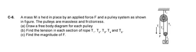
C-6. A mass M is held in place by an applied force F and a ...
Pulley system, find the acceleration and tension | Physics Forums

Pulleys - Physics for K-12 - OpenStax CNX
Solved Determine the natural frequency of the | Chegg.com
Two-Body Problems

Find the motion of mass, m, of the mass-pulley system when it ...

Friction solved problems
Pulleys

Physics 4.8 Free Body Diagrams (8 of 10) 3 Masses on a Table (With Friction)

Pulley and Cables Free Body Diagram in 2 Minutes! (Example)

Pulleys - Physics for K-12 - OpenStax CNX
Horizontal pulley
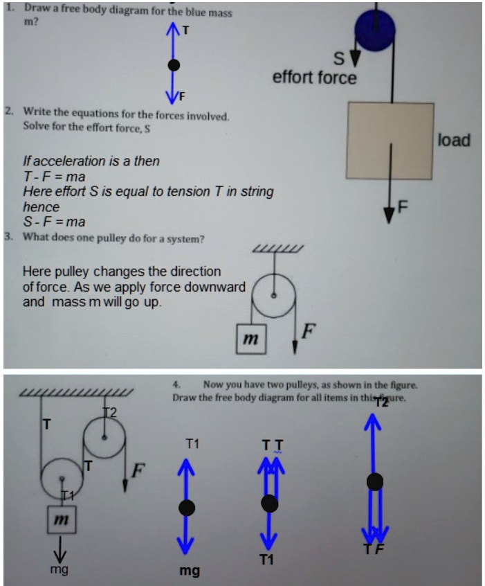
SOLVED:Draw free body diagramn for the blue mass In? S effort ...

Levers and Pulleys in Translating Mechanical Systems

homework and exercises - Choosing signs in free body diagrams ...
Two-Body Problems
Horizontal pulley
FORCES AND FREE BODY DIAGRAMS - ppt download
An object of mass 16 kg is held in place by an applied force ...
0 Response to "42 Pulley System Free Body Diagram"
Post a Comment