38 in a state transition diagram, the circle to the left is the final state.
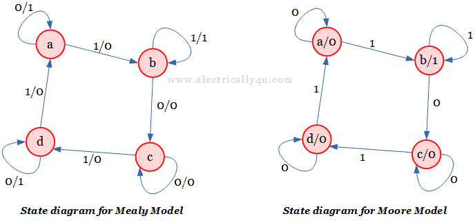
Design 101 sequence detector (Mealy machine ... Prerequisite - Mealy and Moore machines A sequence detector is a sequential state machine that takes an input string of bits and generates an output 1 whenever the target sequence has been detected. In a Mealy machine, output depends on the present state and the external input (x). Hence, in the diagram, the output is written outside the states, along with inputs. 30 Basketball Drills that will motivate and challenge your ... Players are paired with the player across from them in the drill setup. in the diagram at the left, 1 and x1 are paired, 2 and x2 are paired. 3 and x3, and 4 is paired with x4. Use 2 basketballs for the drill. In the example, both x1 and 1 are starting with a basketball. Players pass the ball to their right and then sprint straight across the floor to change spots with their partners before ...
Geometrical analysis of motion schemes on fencing experts ... Such a transformation determines a transition from an initial state to a final state We define a motion scheme as a transition system (V, A, Λ, i, f, τ, μ) realized by motion spaces as follows: V is a finite set of states (or vertices) A is a finite set of transitions (or arrows) Λ is a finite set of time-dependent motion spaces

In a state transition diagram, the circle to the left is the final state.
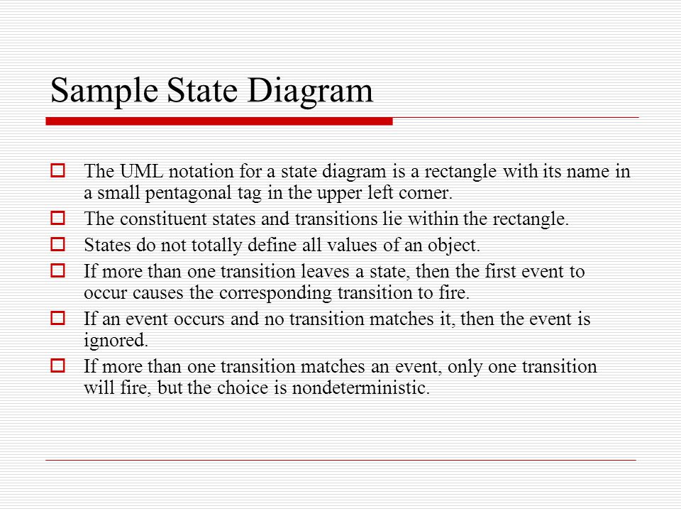
Reviving a failed network through microscopic ... As our final example (Fig. 6 and Supplementary Section 3.3), we consider the gut microbiome, a microbial community whose functional state has been shown to crucially impact human health 32,33. Finite automata Finite State The diagram consists of: 1. The circle represents the state The circle is labeled according to the name of the state. The division of the circle is: a. Single-lined circle means temporary state. A double-lined circle means the final state 2. Arrows represent transitions that occur. Probabilistic teleportation of a quantum dot spin qubit ... First, the Q2-Q3 singlet state \(\left ... the TQD charge states. d Charge stability diagram obtained by sweeping ... can cause a transition to the excited singlet state and ...
In a state transition diagram, the circle to the left is the final state.. Glycolysis : All Steps with Diagram, Enzymes, Products ... It is a universal catabolic pathway in the living cells. Glycolysis can be defined as the sequence of reactions for the breakdown of Glucose (6-carbon molecule) to two molecules of pyruvic acid (3-carbon molecule) under aerobic conditions; or lactate under anaerobic conditions along with the production of small amount of energy. Cause and Effect Graph - Dynamic Test Case Writing ... Cause-Effect Graph is a technique that starts with a set of requirements and determines the minimum possible test cases for maximum test coverage which reduces test execution time and cost. The goal is to reduce the total number of test cases, still achieving the desired application quality by covering the necessary test cases for maximum coverage. P-V and T-S Diagrams - NASA On the figure we show two types of plots that are used to describe changes of state. On the left we have plotted the pressure versus the volume, which is called a p-V diagram. On a p-V diagram, lines of constant temperature curve from the upper left to the lower right. A process performed at constant temperature is called an isothermal process. › 404We apologize for the inconvenience... - United States ... We recently redesigned State.gov. Many pages are now on our most recent Archive page. Please use our search, browse further via our navigation, or return to the Home page. Still can’t find it? Send us a message using our Contact Us form. A URL is helpful when reporting site problems. Thank you for visiting State.gov.
How to create an awesome workflow diagram (and why ... - Cacoo A workflow diagram is a step-by-step, linear representation of a business process from start to finish. It shows how individual tasks, actions, or resources flow between different people or groups. It also shows the actions your team must take to finish a task. Tasks are generally represented as boxes and diamonds, although images or real-life ... Transaction States in DBMS - GeeksforGeeks Transaction States in DBMS. States through which a transaction goes during its lifetime. These are the states which tell about the current state of the Transaction and also tell how we will further do the processing in the transactions. These states govern the rules which decide the fate of the transaction whether it will commit or abort. State Transition Diagram with example in software engineering In a state transition diagram, the states appear as rounded rectangles with ... In a state transition diagram, the circle to the left is the final state.Nov 26, 2012 · Uploaded by Derek Banas Detuning Axis Pulsed Spectroscopy of Valley-Orbital States ... Notably, for each orbital in a dot, the valley ground state (solid line) tends to decay faster than its valley excited counterpart (dotted line). A possible exception is the set of higher excited P5 orbital or valley states in the upper left of (e), as further discussed in the main text. Reuse & Permissions
› transition-diagramTransition Diagram - Javatpoint Transition Diagram. A transition diagram or state transition diagram is a directed graph which can be constructed as follows: There is a node for each state in Q, which is represented by the circle. There is a directed edge from node q to node p labeled a if δ(q, a) = p. In the start state, there is an arrow with no source. ScholarAssignments - Best Custom Writing Services The final check includes: Compliance with initial order details. Plagiarism. Proper referencing. If for some reason we happen to leave a mistake unnoticed, you are invited to request unlimited revisions of your custom-written paper. For more information, check our Revision Policy. We will do our best to make your experience with ScholarAssignments enjoyable. Read full FAQ. … On-shell representations of two-body transition amplitudes ... This work explores scattering amplitudes that couple two-particle systems via a single external current insertion, $2+\mathcal{J}\ensuremath{\rightarrow}2$. Such amplitudes can provide structural information about the excited QCD spectrum. We derive an exact analytic representation for these reactions. From these amplitudes, we show how to rigorously define resonance and bound-state form factors. Predictive Parser in Compiler Design - GeeksforGeeks 18/03/2021 · Make a transition diagram(DFA/NFA) for every rule of grammar. Optimize the DFA by reducing the number of states, yielding the final transition diagram. Simulate the string on the transition diagram to parse a string. If the transition diagram reaches an accept state after the input is consumed, it is parsed. Consider the following grammar –
State Transition Diagram - an overview | ScienceDirect Topics
The Pennsylvania State University bleach (left) and excited state absorption (right) in which the green arrow represents the pump pulse and the red arrow represents the state observed by the probe beam. B) Example of the type of spectra typically obtained from TRIR with a ground state bleach and excited state absorption both present. The blue trace is the ground state
State diagram - Wikipedia
Activity Diagram in UML: Symbol, Components & Example Activity diagrams symbols can be generated by using the following notations: Initial states: The starting stage before an activity takes place is depicted as the initial state; Final states: The state which the system reaches when a specific process ends is known as a Final State; State or an activity box:

UML Diagram Types | Learn About All 14 Types of UML Diagrams
Page Not Found - alexander-goers.de Il y a 2 jours · email protected]
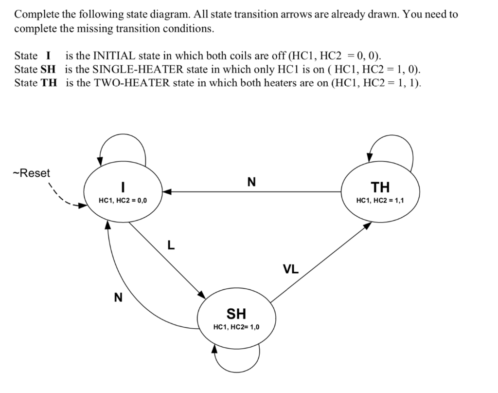
Complete the following state diagram. All state | Chegg.com
Designing Finite Automata from Regular ... - GeeksforGeeks In the above transition diagram, as we can see that state 'V' on getting 'a' as the input it transits to a state 'W' which on getting either 'a' or 'b' as the input it transits to a final state 'X' which on getting either 'a' or 'b' it remains in the state of itself and so on for the remaining states.

Problem Solving: Finite state machines - Wikibooks, open ...
Phase Change: Evaporation, Condensation ... - Study.com Phase change is often shown in a diagram like the one below: Diagram of water phase changes When a substance is in a solid state, it can absorb a lot of energy in the form of heat until it hits ...
Create a UML state machine diagram
State Diagram and state table with solved problem on state ... It clearly shows the transition of states from the present state to the next state and output for a corresponding input. In this diagram, each present state is represented inside a circle. The transition from the present state to the next state is represented by a directed line connecting the circles.
5.state diagrams
Chapter 6 - Carbohydrates - CHE 120 - Introduction to ... 6. Identify each disaccharide in Exercise 4 as a reducing or nonreducing sugar. If it is a reducing sugar, draw its structure and circle the anomeric carbon. State if the OH group at the anomeric carbon is in the α or β position. 7. Melibiose is a disaccharide that occurs in some plant juices. Its structure is as follows: a.

State Machine Diagram - UML 2 Tutorial | Sparx Systems
› state-machine-diagramsUML State Machine Diagrams - Overview of Graphical Notation Optionally it may be placed both within the state machine diagram or composite state and outside the border of the state machine diagram or composite state. Alternatively, the “bracket” notation can also be used for the transition oriented notation. Choice. Choice pseudostate realizes a dynamic conditional branch. It evaluates the guards of ...
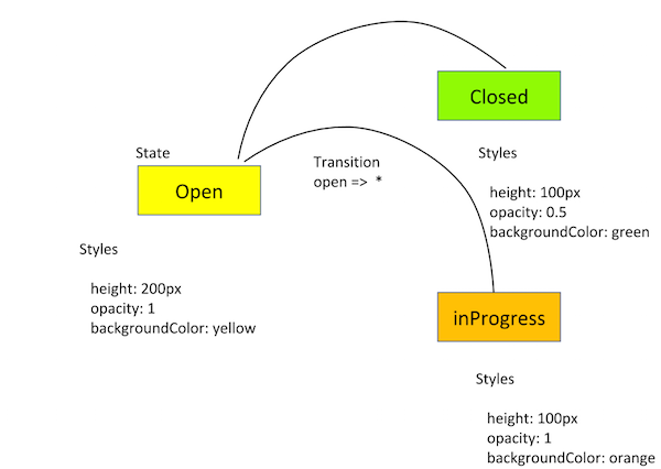
Angular - Animations transitions and triggers
Regular languages and finite automata - GeeksforGeeks 1 is true. L(A) is regular, its complement would also be regular. A regular language is also context free. 2 is true. 3 is false, the DFA can be minimized to two states. Where the second state is final state and we reach second state after a 0. 4 is clearly false as the DFA accepts a single 0.
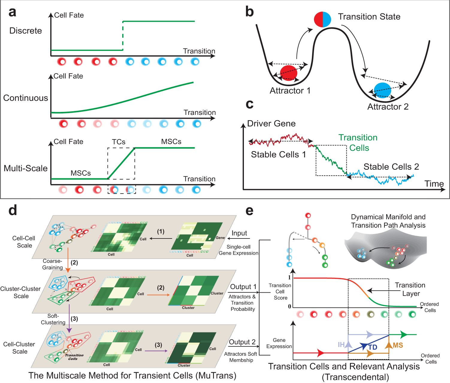
Dissecting transition cells from single-cell transcriptome ...
Difference Between NFA and DFA (With Table) - Ask Any ... On receiving a particular symbol, it moves to another state. When the symbols are exhausted and there is no other symbol left, then the state in which the machine is present is noted. There can be one or more predefined final states.
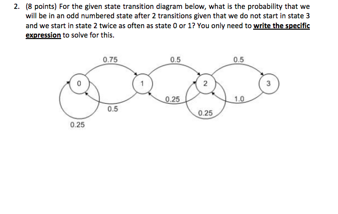
Solved 2. (8 points) For the given state transition diagram ...
UML for Android Engineers - raywenderlich.com In the diagram, the transition from CREATED to STARTED happens when the ON_CREATE happens. In a state diagram, you represent the final state with a circle with a smaller full black circle inside. As the name says, this is the final state, and you cannot exit from it.
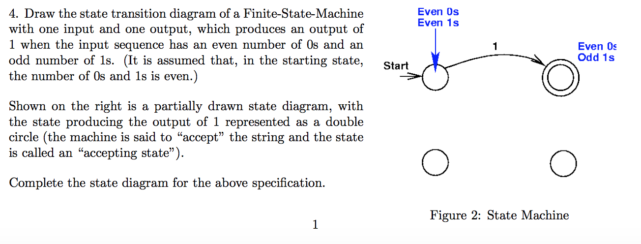
Solved Even Os Even 1s 4. Draw the state transition diagram ...
State Machine Diagram in UML | What is Statechart Diagram? A transition between one state into another state occurs because of some triggered event. To draw a state diagram in UML, one must identify all the possible states of any particular entity. The purpose of these UML diagrams is to represent states of a system. States plays a vital role in state transition diagrams.
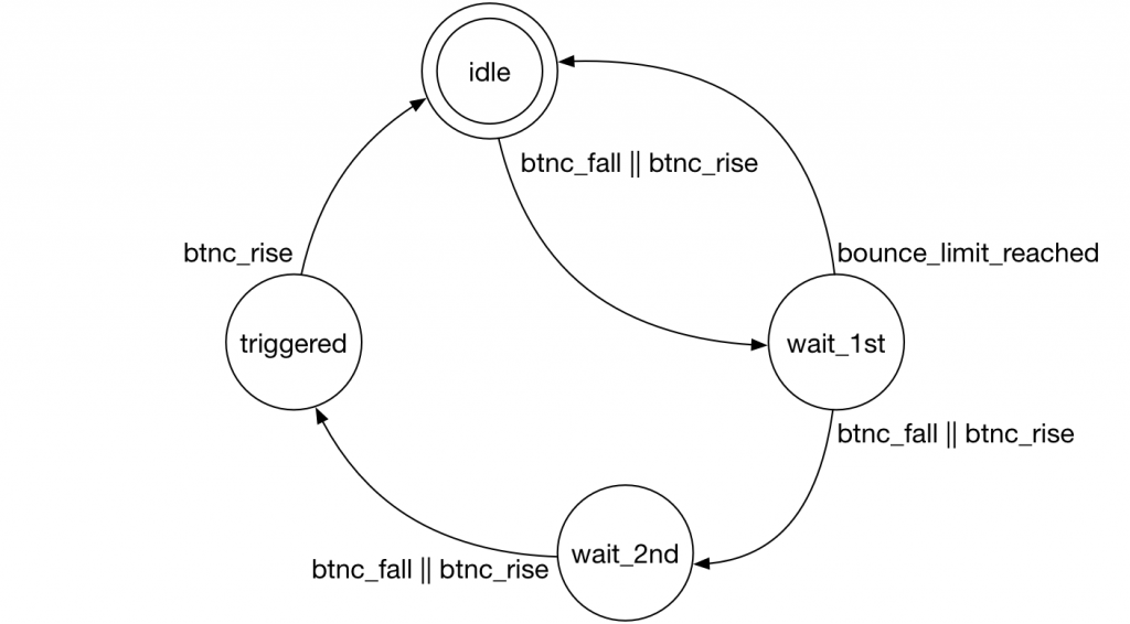
Tutorial 9: Measuring Button Bounce | Beyond Circuits
Chiral control of quantum states in non-Hermitian spin ... Spin-orbit coupling is an essential mechanism underlying quantum phenomena such as the spin Hall effect and topological insulators1. It has been widely studied in well-isolated Hermitian systems ...
State Diagram and state table with solved problem on state ...
Finite Automata Transition Diagram. A transition diagram is a directed graph which can be constructed as follows: There is a node for each state in Q, which is represented by the circle. There is a directed edge from node q to node p labeled a if δ(q, a) = p. In the start state, there should be an arrow with no source. Final states or Accepting states are ...

The state transition diagram of WikiTUI. Shapes with dotted ...
A Time Refinement Framework Based on iUML-B State Machine In the timed automata patterns, a timed automaton is abstracted as a triangle. The left vertex or the circle attached to the left vertex represents the initial state of the timed automata; the right side represents its final state. Figure 1 shows the Deadline timed automata pattern.

State Transition Diagram - an overview | ScienceDirect Topics
What is State Transition Testing? Diagram, Technique, Example Two main ways to represent or design state transition, State transition diagram, and State transition table. In state transition diagram the states are shown in boxed texts, and the transition is represented by arrows. In state transition table all the states are listed on the left side, and the events are described on the top.
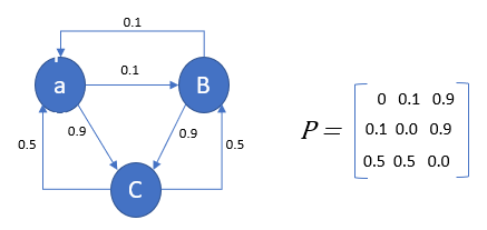
Markov Chain Analysis and Simulation using Python | by Herman ...
Chapter Six Flashcards | Quizlet

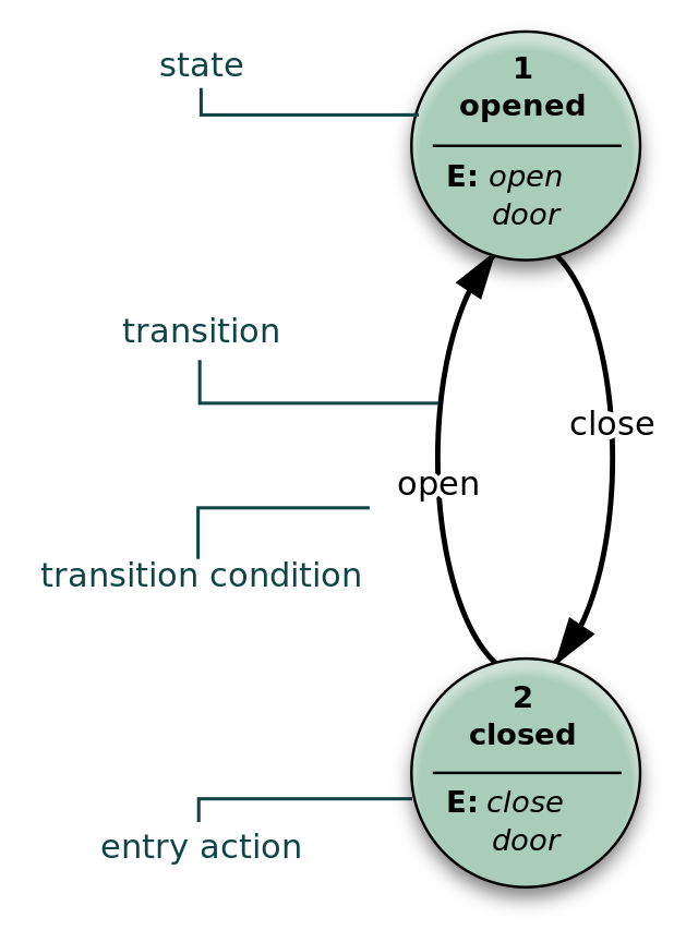
State transition diagram for searching for a door. First the ...
ULM Opens Final Sun Belt Road Swing at Surging Georgia ... Georgia State had five cancellations earlier this season, including four league games. All five starters return from last year's team that won the East Division regular-season title and advanced to the Sun Belt Tournament Championship Game. "This team really relies on its guard play. Georgia State likes to get out and run in transition.
Application Design Patterns: State Machines - NI
› uml › uml-state-diagramUML State Diagram: A Useful Guide - Edraw - Edrawsoft Feb 15, 2022 · A UML state diagram also referred to as a state machine, holds information of an object with regards to the state the object is in and the transitions in between. By visualizing an object's behavior and its possible transitive states, a state diagram, also a statechart diagram gives you a better understanding of an object's behavior.
PLOS Computational Biology: Modeling effects of voltage ...
Probabilistic teleportation of a quantum dot spin qubit ... First, the Q2-Q3 singlet state \(\left ... the TQD charge states. d Charge stability diagram obtained by sweeping ... can cause a transition to the excited singlet state and ...
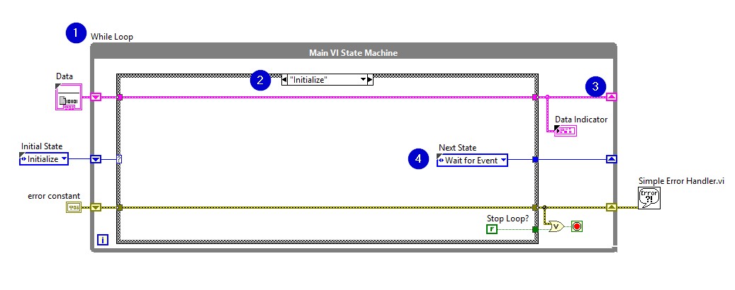
Application Design Patterns: State Machines - NI
Finite automata Finite State The diagram consists of: 1. The circle represents the state The circle is labeled according to the name of the state. The division of the circle is: a. Single-lined circle means temporary state. A double-lined circle means the final state 2. Arrows represent transitions that occur.

State Machine Diagram - UML 2 Tutorial | Sparx Systems
Reviving a failed network through microscopic ... As our final example (Fig. 6 and Supplementary Section 3.3), we consider the gut microbiome, a microbial community whose functional state has been shown to crucially impact human health 32,33.
PPT - State Transition Diagrams PowerPoint Presentation, free ...

Set Breakpoints to Debug Charts - MATLAB & Simulink

State transition diagram for searching for a door [22 ...
.jpg)
Untitled Document
State Diagrams A state diagram is a graph whose nodes are ...

tikz pgf - drawing state diagrams / graphs in matplotlib with ...

UML state machine - Wikipedia
![MCQ's] Theory of Computer Science - Last Moment Tuitions](https://lastmomenttuitions.com/wp-content/uploads/2020/12/14.jpg)
MCQ's] Theory of Computer Science - Last Moment Tuitions
Software Design: State Diagram
Entropy | Free Full-Text | Integrated Information Theory and ...
What is State Transition Testing? Diagram, Technique, Example

Fun with Arduino 17 Railway Crossing State Transition Diagram ...

Finite-State Machine - an overview | ScienceDirect Topics
Transition Diagram - Javatpoint

State transition diagram. The labels on the nodes and edges ...
Delphi: State Diagrams- Dt2t (previously known as Dt2r)
0 Response to "38 in a state transition diagram, the circle to the left is the final state."
Post a Comment