39 6 wire regulator rectifier wiring diagram
Bridge Rectifier : Circuit Diagram, Types, Working & Its Applications The bridge rectifier circuit diagram consists of various stages of devices like a transformer, Diode Bridge, filtering, and regulators. Generally, all these blocks combination is called a regulated DC power supply that powers various electronic appliances. The first stage of the circuit is a transformer... Pitbike Rectifier/Regulator Wiring Diagram - YouTube In this video, I show how to wire the rectifier/regulator to the stator of the pitbike. I show how to make connections for the headlight. I also show how to...
Piaggio Tech Manuals | PDF | Rectifier | Direct Current Rectifier Earth wires are - Yellow / green. Indicator Regulator & Relay Yellow wire is AC supply. * Three completely separate circuits for AC, DC & ignition. AC is full wave and regulated DC is half wave rectified and regulated Ignition is the self powered CDI type typical on our two stroke scooters.
6 wire regulator rectifier wiring diagram
Motorcycle Regulator, Rectifier Tester Circuit - Homemade Circuit... To test the Regulator, its wires are connected to the test circuit as shown. The red wire is not used. The op-amp IC1-A (along with C1, R1, R2, R3, R5 and If one or both LEDs blink, it indicates that the rectifiers are short (bad). p.s. I have tested the above explained motorcycle regulator, rectifier tester... Producing A Fix For The Regulator/rectifier Wiring Issue | Forum VFR TECH. Modifications. Producing A Fix For The Regulator/rectifier Wiring Issue. Facebook. Twitter. I checked the wiring diagram to be sure there wasn't something designed to make the reading low on purpose….nothing. As a test I jumpered a wire from the positive terminal to the sensor... PDF 15/20 EFI FourStroke Wire Color Code Abbreviations. Fuel System Wiring Diagram. The voltage regulator circuit and the electric starting circuit are protected from overload by 20‑amp and 15‑amp fuses, respectively. e - Engine coolant temperature (ECT) sensor (behind voltage regulator/rectifier wires).
6 wire regulator rectifier wiring diagram. 6 Wire Thermostat Wiring Color Code / 8 best Circuit Symbol images... Honeywell Thermostat Wiring Diagram 6 Wire Best 7 Wire ... from tonetastic.info. Wiring color chart for air conditioners and heat pumps. In this article, i am going to explain the function and wiring of the most common home climate control thermostats. 02 Suzuki Motorcycle Rectifier Wiring Diagram - Wiring Diagram... Regulator Rectifier Combo With Points Wiring Diagram. Suzuki Wire Diagram Reading Industrial Wiring Diagrams. 2002 Gsx 750 Wiring Diagram Wiring Diagram. Us 16 55 8 Off Motorcycle Regulator Rectifiers 5 Wires Plug For Yamaha Fzr600 Fz6r Fz6s Yzf R1 R6 Xvs1100 V Star Xvs... 6 Wire Regulator Rectifier Wiring Diagram - Wiringpedia 12 12v Rectifier Regulator Diagram Motorcycle Motorcycle Diagram Wiringg Net Motorcycle Wiring Voltage Regulator Electrical Diagram. 110cc Chinese Atv Wiring Diagram Unique Nice 6 Pin Cdi With 110cc Motorcycle Wiring 150cc Scooter 150cc Go Kart. PDF 010-ELV-116 for 7004-RR150.indd | REGULATOR/RECTIFIER Regulator/rectifier. Wiring guide. 010-ELV-116 regulator/rectifier 7004-RR150. Tech Support: 360-687-4530 tech_support@trailtech.net.
Rectifier Regulator Wiring Diagram 5 pin regulator rectifiier wiring diagram Sana makatulong po ito sainyo mga bro. Para sa iba pang vidio wag nyo pong kalimutan ... Paano ang connection pag nag convert ka ng 4 wires regulator rectifier sa sa 5 wires regulator rectifier. Sana makatulong sa inyo ... Regulator/Rectifier Replacement bike's wiring harness that leads through the fuse box and eventually to the positive battery terminal. On 6 wire units, that wire is a “sense” wire which ...7 pages Voltage Regulator / rectifier units Regulator/Rectifier unit for the SOHC Honda CB650 four. (Will not mount up to the DOHC models Click here for a diagram to see how this unit would wire into your bike. This unit requires a plugs into the original regulator and rectifier connectors on the wiring harness but requires custom mounting. Wiring a Rectifier/Regulator? | Motored Bikes | Motorized Bicycle... Wiring a Rectifier/Regulator? Thread starter AnvilBlockForge. A rectifier and capacitor just changes AC to DC. A regulator keeps the DC output voltage steady so that it doesn't increase with RPM.
Regulator Rectifier wiring | Adventure Rider Regulator Rectifier wiring. Discussion in 'Thumpers' started by delormea397, Jun 16, 2018. in order to get full wave rectification from the lighting coil you need both ends of that coil to go to the rectifier. right now, one end is grounded at the stator ring, and connects to the frame (eventually) through the... Alternator Wiring Diagram: A Complete Tutorial | EdrawMax 03 Alternator Wiring Diagrams. 04 Use EdrawMax for Wiring Diagram Creation. What is an Alternator? The alternator comprises a cooling fan, voltage regulator, rotor, stator, diode bridge rectifier, slip rings, slip ring end bearings, carbon brushes, pulley. Putting a 6 wire rectifier on a 5 wire bike?? - Bike Chat Forums Nov 8, 2008 — What bike is it? , in that my NTV has a reg rec with two green and two red , but looking closely at the circuit diagram the green and reds both ...8 posts · Can a 6 wire rectifier be put on a bike with a 5 wire rectifier. The bike's wires are 3 yellow ... 4 Pin Regulator Rectifier Wiring Diagram - Wiring Diagram Database Anyone got a wiring diagram for a china pitbike regulatorrectifier. Provided below is an online pdf document for lamberts bikes 4 pin regulator rectifier wiring diagram. Chinese 110cc Atv Wiring Diagram View Diagram 110cc Basic Wiring. 4 Wire Rectifier Wiring C5 Schwabenschamanen De.
Charging System Diagnostics - Rectifier/Regulator Upgrade This is about replacing the standard equipment Regulator/Rectifier with a more efficient component. You can do this in event of failure rather than replace with Ask on the forum for your particular model which one you should check if in doubt. Next, examine the wires and connectors between the stator...
How to connect 12V 6 Wires Voltage Rectifier Regulator ... Complete kit with Extra Heavy Duty Finned ADJUSTABLE Voltage Regulator preset to ... How do I connect 12V 6 Wires Voltage Rectifier Regulator 185516061 for ...1 answer · 0 votes: When all else fails, read the instructions. Did you get an instruction sheet? Complete ...
PDF Service Refer to applicable wiring diagram. 2. Remove wires from terminals at each end and using an ohmmeter, check each wire end to end for continuity or The basicoperation of the generatorandAC controls involvesthestator,voltage regulator, exciter field and armature, afull wave bridge rectifier...
DIY Rectifier Regulator - RIBnet Forums This is a wiring diagram I tracked down showing a similar 6 wire RR in a bike circuit. If I understand your comment correctly, do I take it that if there is no load then a rectifier/regulator would fail? affirmative but if you set it up so you can unplug it from the AC supply you won't have the problem or...
Rectifier Regulator Wiring Diagram 5 pin regulator rectifiier wiring diagram Sana makatulong po ito sainyo mga bro. Para sa iba pang vidio wag nyo pong kalimutan ... Rectifier Regulator 5ipn Installation Manual & Diagram Manual installation Rectifier Regulator 5Wires Deffernce Colors wires Step ...
PDF 08_3211348_en_OM.pdf WIRING DIAGRAM. Components A6 CDI controller B1 Throttle position sensor B3 Wheel speed sensor E6 Thermoswitch (EXC-F SIX DAYS) G1 Battery G2 Generator H1 Right rear flasher H2 Left front flasher H3 Left rear flasher H4 Right front flasher H5 Brake/tail light H7 Parking light H9 License plate...
Alternator Wiring Diagrams and Information - BRIANESSER.COM Wiring instructions for the early GM Delco Remy external regulated alternator. How to wire an external voltage regulator on a GM vehicle. This conversion to D/C takes place in the Bridge Rectifier . Diodes have the property of allowing current to flow in only one direction, while blocking current flow in...
Diode less Rectifier Wiring diagram Schematic | Panel switch wiring Diode less Rectifier Circuit Diagram . It`s common knowledge that when working with single-supply op amps, implementing simple functions in a bipolar signal environment can be difficult. Sometimes additional op amps and other electronic components are required.
Regulator Rectifier Wiring 5 pin regulator rectifiier wiring diagram Sana makatulong po ito sainyo mga bro. Para sa iba pang vidio wag nyo pong kalimutan ... Paano ang connection pag nag convert ka ng 4 wires regulator rectifier sa sa 5 wires regulator rectifier. Sana makatulong sa inyo ...
PDF Rectifier 105 Six-Phase Star Rectifier Circuit . . ... . 107 Six-Phase Full-Wave Bridge The energy band diagram of intrinsic silicon is shown in Figure 4. The intrinsic silicon valence band leads to some kind of a heat dissipator, which is usually nothing more than a printed-circuit wiring pattern.
PDF Chapter 1 | Explanation of Rectifier / regulator wiring * This diagram shows the early 50cc and 80cc two stroke wiring using a five pin connector on the rectifier / regulator. AC is full wave and regulated DC is half wave rectified and regulated Ignition is the self powered CDI type typical on our two stroke scooters.
PDF Table of Contents See individual model wiring diagrams at the rear of this manual. voltage regulators used on these sets-transformer. and electronic (solid state). Use a Wheatstone Bridge or digital ohmmeter for this test. Disconnect main rotorfield leadswhich connectto rotating rectifier assembliesat F1+and F2
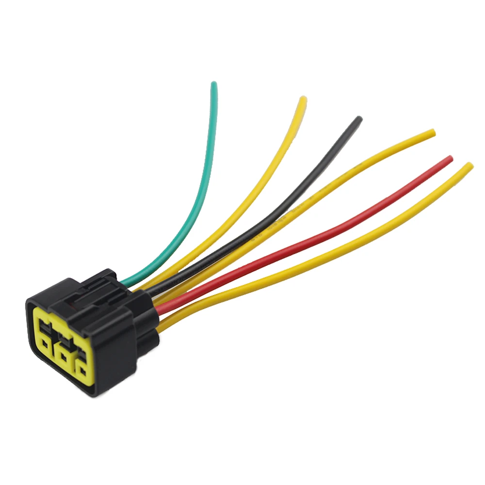
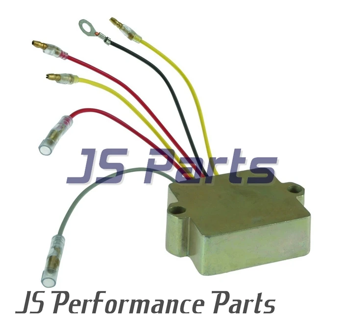
6 Wires Motorcycle Regulator Rectifier Plug Voltage Regulator Connector for Kawasaki Z1000SX ZX1000 Z250 Z300 Z750 Z800 Z1000
5 Pin Regulator Rectifier Wiring Diagram / Universal 12v 5 Pin Wire... Rectifier regulator wiring diagram for honda motorcycle 6. B+ regulator rectifier & regulator * this diagram shows the early 50cc and 80cc two stroke wiring using a five pin connector on * eight pin rectifier / regulator incorporates the indicator relay and oil light check function.
Voltage Regulator/Rectifier Wiring Diagram; Electrical... | ManualsLib Husqvarna 2013 TC 250R Manual Online: voltage regulator/rectifier wiring diagram, Electrical Starting System (Te-Txc). Tc Te-Txc H11002 H10123 Te - Txc Electrical Starting System (Te-Txc) The Starting System Is Composed Of: 1 - Battery (5); 2 - Solenoid Starter (4); - Starter Motor...
Gy6 4 Pin Regulator Rectifier Wiring Diagram For Your Needs Print the wiring diagram off and use highlighters in order to trace the circuit. I print the schematic and highlight the signal I'm diagnosing in order to make sure I'm staying on the particular path. Gy6 4 Pin Regulator Rectifier Wiring Diagram Source: atvconnection.com.
PDF 15/20 EFI FourStroke Wire Color Code Abbreviations. Fuel System Wiring Diagram. The voltage regulator circuit and the electric starting circuit are protected from overload by 20‑amp and 15‑amp fuses, respectively. e - Engine coolant temperature (ECT) sensor (behind voltage regulator/rectifier wires).
Producing A Fix For The Regulator/rectifier Wiring Issue | Forum VFR TECH. Modifications. Producing A Fix For The Regulator/rectifier Wiring Issue. Facebook. Twitter. I checked the wiring diagram to be sure there wasn't something designed to make the reading low on purpose….nothing. As a test I jumpered a wire from the positive terminal to the sensor...
Motorcycle Regulator, Rectifier Tester Circuit - Homemade Circuit... To test the Regulator, its wires are connected to the test circuit as shown. The red wire is not used. The op-amp IC1-A (along with C1, R1, R2, R3, R5 and If one or both LEDs blink, it indicates that the rectifiers are short (bad). p.s. I have tested the above explained motorcycle regulator, rectifier tester...








.jpg?x-oss-process=image/auto-orient,1/quality,q_70/format,webp)


0 Response to "39 6 wire regulator rectifier wiring diagram"
Post a Comment