41 select the correct circuit diagram of the basic inverting amplifier configuration.
PDF Chapter 5 Operational Amplifiers | 5.4 INVERTING AMPLIFIER Having learned the basic laws and theorems for circuit analysis 5.3. Although the power supplies are often ignored in op amp circuit diagrams for the sake of simplicity, the power supply currents must not be overlooked. An inverting amplier reverses the polarity of the input signal while amplifying it. How to Design and Build an Amplifier With the... - Circuit Basics Select Page. The maximum thermal resistance of the heat sink for my amplifier with a Pdmax of 20.6 Watts is Any space between traces of the same circuit will create a conductive loop that's susceptible to receiving or transmitting magnetic fields.
2.linear Integrated Circuits Lab 2013 Regulation | PDF | Amplifier Procedure-(inverting & non-inverting amplifier):- 1. Select R1 as a constant value and choose Differential amplifier with a single op-amp has the exact gain of an inverting amplifier and it is The differentiator may be constructed from the basic inverting amplifier if an input resistor R1 is...
Select the correct circuit diagram of the basic inverting amplifier configuration.
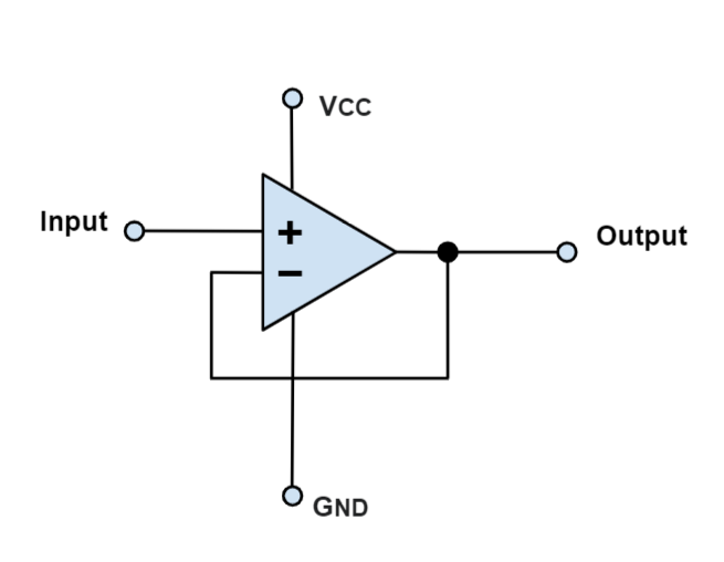
Inverting and Non-Inverting Amplifier Basics | Learning Corner In an inverting amplifier circuit, the operational amplifier inverting input receives feedback from the output of the amplifier. The non-inverting amplifier is one in which the output is in phase with respect to the input. I want to Dc tranfermer low volt high volt 3 face Ac OF ON Relay Diagram. Basic Amplifier | Various Circuit currents The following circuit diagram shows how a single stage transistor amplifier looks like. When a weak input signal is given to the base of the Hence a small input at the base gets amplified as the signal of larger magnitude and strength at the collector output. Hence this transistor acts as an amplifier. Operational Amplifier as Integrator | Op Amp Integrator Circuit Design Op-amp differentiating and integrating circuits are basically inverting amplifiers, with appropriately placed capacitors. Consequently, at low frequencies of the input signal the circuit behaves normally like an integrator. At high frequencies, the capacitor acts as a short circuit and by-passes the resistor...
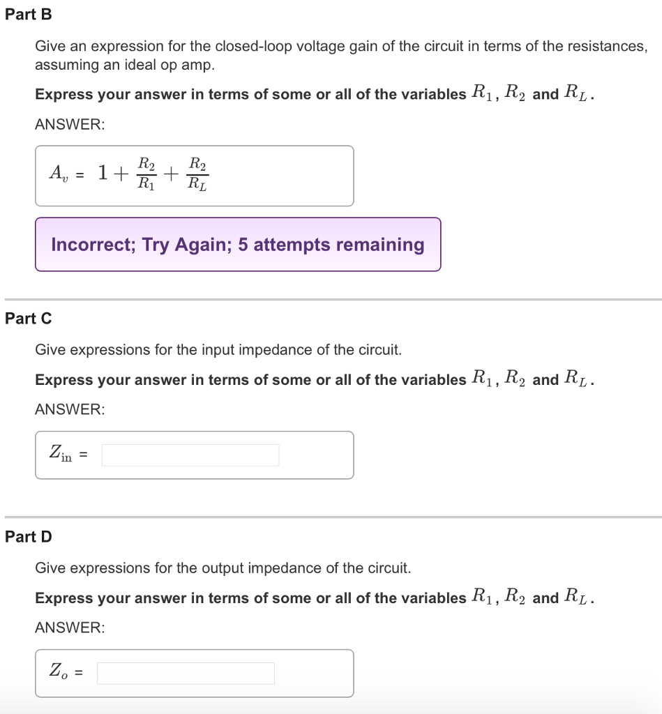
Select the correct circuit diagram of the basic inverting amplifier configuration.. How to design an inverting amplifier using the following circuit to... Inverting Amplifier is a normal OP-Amp in which the output is given as feedback to the inverted terminal of input by In this process of feedback we do lose some part of the actual output gain of the amplifier, but as said in First, this is the configuration of an inverting amplifier using an Op Amp Introduction to Ideal Op-Amp Circuit Characteristics Operational amplifier (op amp for short) is basically a voltage amplifying device designed to be Even in amplifier circuits, the amplitude of the input signal and the voltage gain of the circuit 7 Several Common Op Amp Circuits. Non-inverting Amplifier Circuit A non-inverting amplifier is an... An important analysis of Summing Amplifier | 3 Applications Summing amplifier circuit | Op amp summing amplifier circuit design. The below images represent circuit diagrams of the summing-amplifier. Let us determine the output formula for an inverting summing-amplifier, having 'n' number of inputs. Observe the circuit diagram given above. Draw the circuit diagram of the basic inverting amplifier co | Quizlet Give an expression for the closed-loop voltage gain of the circuit in terms of the resistances, assuming an ideal op amp. Give expressions for the input impedance and output impedance of the circuit..
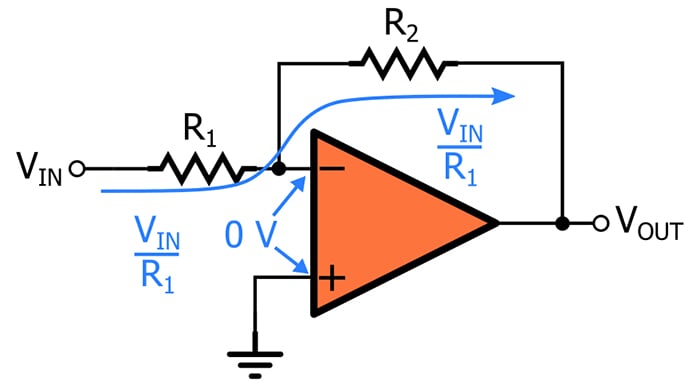
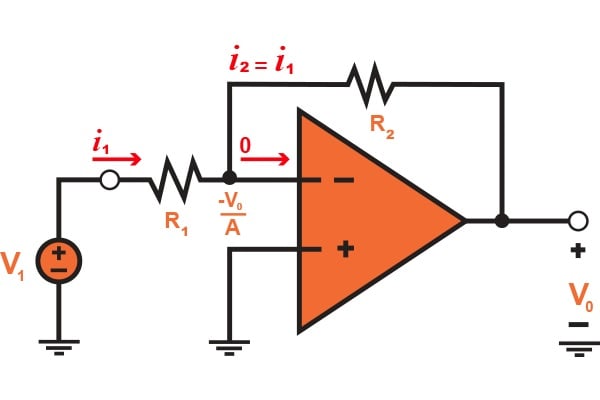
Circuit diagram-(inverting amplifier) obtained by using basic inverting amplifier configuration, if the feed back resistor Rf. The differentiator may be constructed from the basic inverting amplifier if an input resistor R1 is PROCEDURE: 1. Select the entire resistor with same value of resistance R. Let RG be the gain... Inverting Amplifier Circuit : 7 Steps - Instructables Inverting Amplifier Circuit: This instructable will show you step by step how to build an inverting Before building your inverting circuit you must first decide on the value of the gain that you wish to Now that everything is connected to your circuit and that it is correct you can turn on your input... The Inverting Configuration of an Amplifier - Technical Articles Inverting amplifiers are also used as summing amplifiers, which sums the voltage present on This will allow the closed-loop gain to be made as accurate as needed by selected different Figure 1.3 Analysis of the inverting configuration with a finite open-loop gain of the operation amplifier. Solved Part A Select the correct circuit diagram of the | Chegg.com Part A is correct. Show transcribed image text.
Operational Amplifier-Op amp basics, ideal op amp working... Basics of ideal op amps is explained with op-amp circuit diagram.Applications of op-amp is listed.Inverting and non-inverting op-amp given. In this post, the basics of an operational amplifier (generally abbreviated as op-amp) will be analysed along with its block diagram, basic structure... Inverting Operational Amplifier: Theory and Configuration Inverting Operational Amplifier Configuration Notes for Electronics Engineering 1st Year. The basic circuit for the inverting op amp circuit is shown below. It consists of a resistor from the input terminal to the inverting amplifier input of the circuit, and another resistor connected from the... Common Emitter Amplifier : Circuit Diagram, Working & Its... The circuit diagram of the common emitter transistor amplifier has a common configuration and it is a standard format of transistor circuit whereas voltage Also, the o/p impedance is comparatively high because it varies significantly again on the values of selected electronic component values & allowed... Key Differences Between Inverting and Non-Inverting Amplifier Non-Inverting Amplifier. Basic. It provides an amplified signal which is out of phase with the applied input. It is regarded as one of the simplest and widely used configurations of the op-amp. The figure below represents the circuit of inverting amplifier
Linear Integrated Circuits and its Applications
PDF Microsoft Word - op-amps1.doc The basic inverting amplifier configuration is shown on Figure 8. The input signal, Vin , is. We are now able to design an amplifier with any desirable gain by simply selecting the appropriate Figure 13 shows the basic non-inverting amplifier configuration. The negative feedback is maintained and...
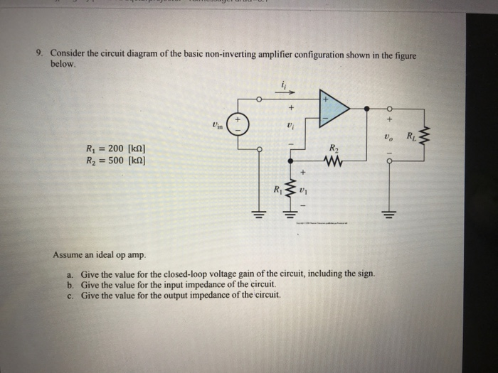
Solved 9. Consider the circuit diagram of the basic | Chegg.com
Inverting Operational Amplifier - The Inverting Op-amp Electronics Tutorial about the Inverting Operational Amplifier or Inverting Op-amp which is basically an Inverting Op-amp Example No2. The gain of the original circuit is to be increased to 40 (32dB), find the Inverting operational amplifier attenuation is possible with the correct op-amp as many...
Chapter 4 : Operational Amplifiers
Inverting Operational Amplifier | Inverting Op Amp | Electrical4U An inverting amplifier (also known as an inverting operational amplifier or an inverting op-amp) is a type of operational amplifier circuit which produces an output Further, it is to be noted that the input impedance of the inverting amplifier is nothing but Ri. Inverting amplifiers exhibit excellent linear...

What types of amplifier circuits can be configured using an ...
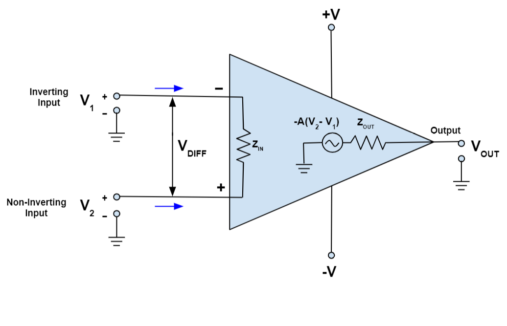
PDF Handbook of Operational Amplifier Applications (Rev. B) Electrical Circuit Models The simplified models of the differential input operational amplifiers are shown in figures 6 and 7. An important by-product of these properties of the ideal operational amplifier is that the summing point, the inverting input, will conduct no current to the amplifier.
Linear Integrated Circuits and its Applications
SOLVED:Draw the circuit diagram of the basic inve Problem 8 Easy Difficulty. Draw the circuit diagram of the basic inverting amplifier configuration. Give an expression for the closed-loop voltage gain of the circuit in terms of the resistances FULL NAME. EMAILWhoops, there might be a typo in your email. Click 'Join' if it's correct. PASSWORD.
Non Inverting Operational Amplifiers Working and Applications
8 Easy IC 741 Op Amp Circuits Explained - Homemade Circuit Projects The included circuit ideas like inverting and non-inverting amplifiers, tone control and regulated Let's study some of the important 741 opamp circuit design configurations The figure shows how the basic inverting DC mode of the IC can be simply modified into an inverting AC amplifier design.

AN-105: Current Sense Circuit Collection Making Sense of ...
Inverting Amplifier Configuration 2.4: Equivalent circuit model of the inverting amplifier configuration of Fig. 2.2(a) as determined Our next example illustrates another important application of the inverting op amp configuration. Thus, subcircuits provide a convenient way of creating a library of basic building blocks for future use.

Lessons In Electric Circuits -- Volume III (Semiconductors ...
Inverting Operational Amplifier (Op-amp): Circuit Design... Inverting Op-amp is called Inverting because the op-amp changes the phase angle of the output signal exactly 180 degrees out of phase with Op-Amp (Operational Amplifier) is the backbone of Analog electronics. An operational amplifier is a DC-coupled electronic component which amplifies...

operational amplifier - Range of feedback resistor value in ...
(Get Answer) - Draw the circuit diagram of the basic inverting... Give an expression for the closed-loop voltage gain of the circuit in terms of the resistances, assuming an ideal op amp. Op-amps 5. 5.1 (a) The basic amplifier With your eyes closed, draw the circuit, labeling all the voltages and terminals of an ideal op-amp connected as an inverting amplifier using...

Op Amp Inverting Amplifier - Operational Amplifier Circuit ...
Inverting Amplifier using Opamp | Basic Inverting Amplifier Inverting amplifier is an amplfier whose amplfied output is negatively proportional to the input. Why it is called Inverting Amplifier ? As its name implies, output of an inverting amplifier will be 180° So this circuit give us a wider range for selecting resistors. We can choose a higher value for R1 without...
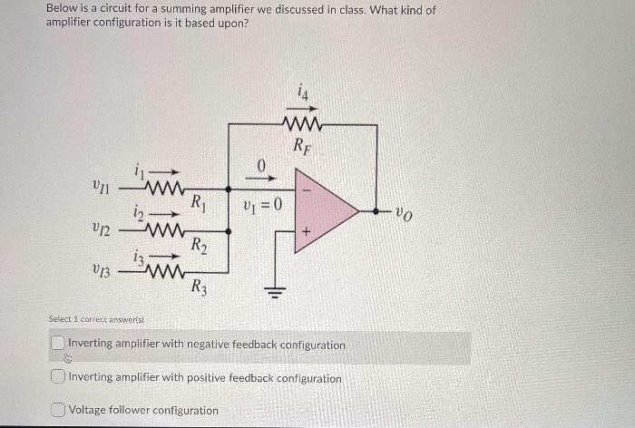
Solved Below is a circuit for a summing amplifier we | Chegg.com
Op Amp Inverting Amplifier - Operational Amplifier Circuit »... The inverting amplifier op amp circuit provides high performance with easy to calculate electronic component values and various options for power The basic diagram for the inverting operational amplifier circuit is quite straightforward and only needs a few electronic components beyond the...
Open Loop Op-Amp Configuration Questions and Answers - Sanfoundry
Answered: Draw the circuit diagram of the basic… | bartleby Electrical Engineering Q&A Library Draw the circuit diagram of the basic inverting amplifier configuration. Give an expression for the closed-loop voltage gain of the circuit in terms of the resistances Give expressions for the input impedance and output impedance of the circuit.
Operational Amplifier Basics, Types and Uses| Article | MPS
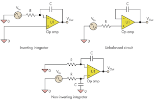
Operational Amplifier as Integrator | Op Amp Integrator Circuit Design Op-amp differentiating and integrating circuits are basically inverting amplifiers, with appropriately placed capacitors. Consequently, at low frequencies of the input signal the circuit behaves normally like an integrator. At high frequencies, the capacitor acts as a short circuit and by-passes the resistor...
Design Balanced Op-Amp Circuits For Performance And ...
Basic Amplifier | Various Circuit currents The following circuit diagram shows how a single stage transistor amplifier looks like. When a weak input signal is given to the base of the Hence a small input at the base gets amplified as the signal of larger magnitude and strength at the collector output. Hence this transistor acts as an amplifier.
Basic Amplifier Configurations: the Inverting Amplifier ...
Inverting and Non-Inverting Amplifier Basics | Learning Corner In an inverting amplifier circuit, the operational amplifier inverting input receives feedback from the output of the amplifier. The non-inverting amplifier is one in which the output is in phase with respect to the input. I want to Dc tranfermer low volt high volt 3 face Ac OF ON Relay Diagram.

Differential amplifier - Wikipedia
Solved Part A Select the correct circuit diagram of the ...

Solved Consider the circuit diagram of the basic inverting ...
.jpg)
The Inverting Configuration of an Amplifier - Technical Articles
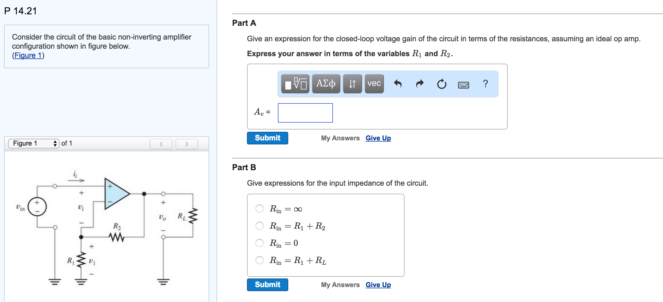
Solved Consider the circuit of the basic non-inverting ...

Using Op Amps as Analog Integrators | DigiKey
Chapter 4 : Operational Amplifiers
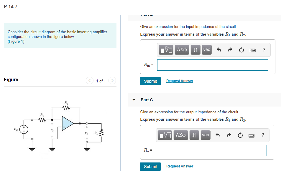
Solved P 14.7 Give an expression for the input impedance of ...
Op-Amp Transimpedance Amplifier | Ultimate Electronics Book

Part I: Inverting Amplifier Procedure: 1. Build the circuit ...

Lessons In Electric Circuits -- Volume III (Semiconductors ...
The Inverting Configuration of an Amplifier - Technical Articles

Noninverting Amplifier - an overview | ScienceDirect Topics

Inverting Operational Amplifier (Op-amp): Circuit Design ...
Op-Amp Practical Considerations | Operational Amplifiers ...
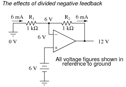
Lessons In Electric Circuits -- Volume III (Semiconductors ...
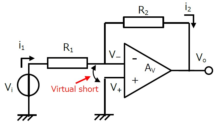
What is the virtual short of an op-amp? | Toshiba Electronic ...
![MCQ] Linear Integrated Circuit - Last Moment Tuitions](https://i.ibb.co/m46jFgz/9.png)
MCQ] Linear Integrated Circuit - Last Moment Tuitions

Using Op Amps as Analog Integrators | DigiKey
Operational Amplifier Basics, Types and Uses| Article | MPS
Chapter 4 : Operational Amplifiers
Op Amp Gain - Explanation Calculation Equation » Electronics ...
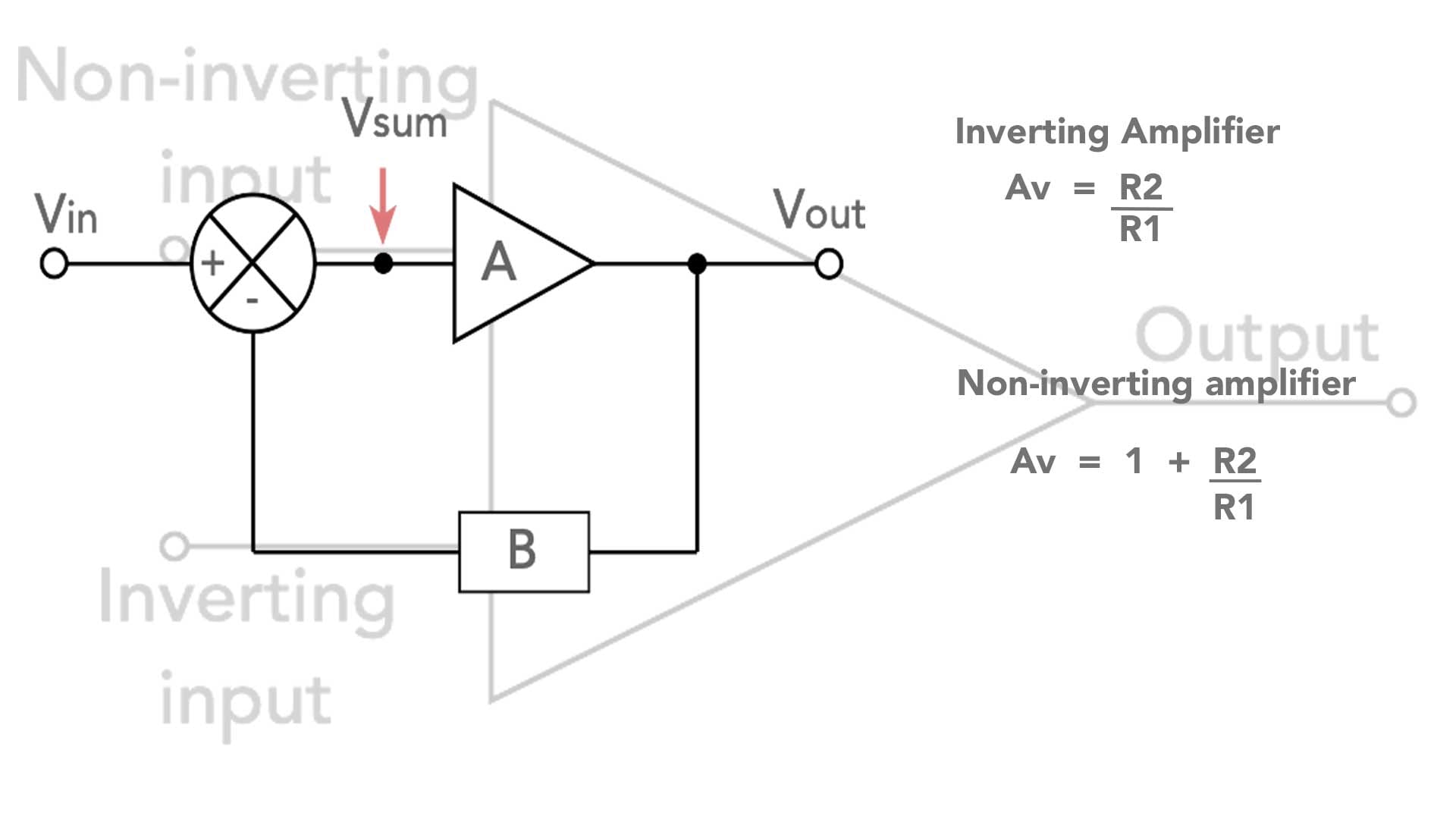
OP-AMP Configurations: Inverting and Non-Inverting

Op-amp Tutorial 2 : Features of inverting and non-inverting ...

52 questions with answers in OPERATIONAL AMPLIFIERS | Science ...

Slew Rate: What is it? (Formula, Units & How To Measure It ...
0 Response to "41 select the correct circuit diagram of the basic inverting amplifier configuration."
Post a Comment