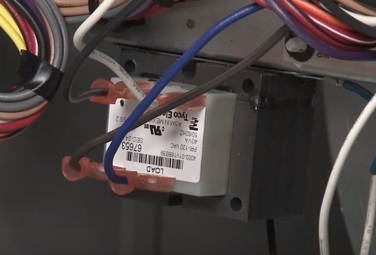
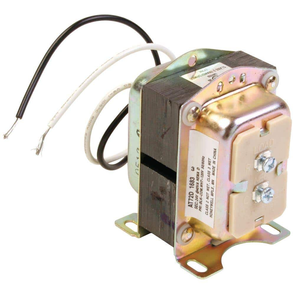
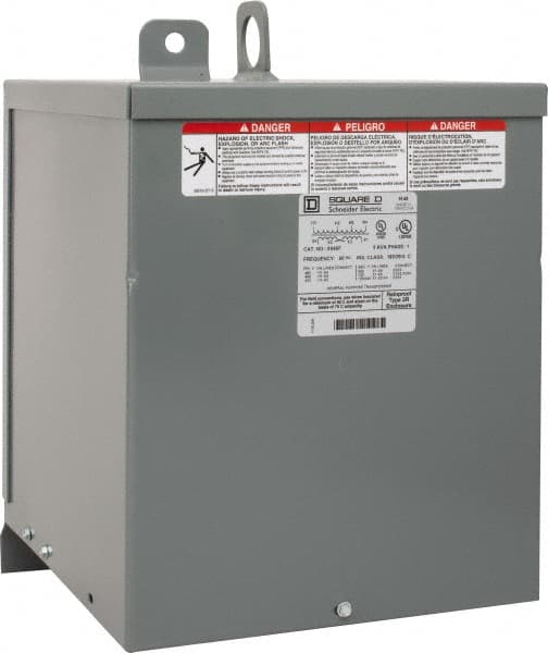
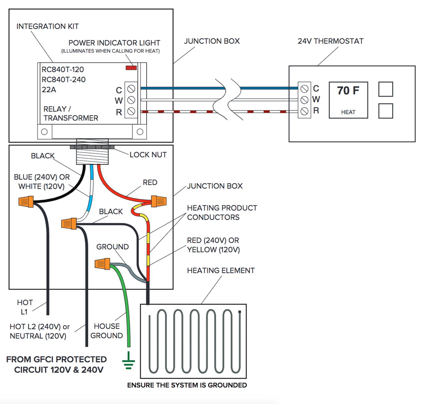
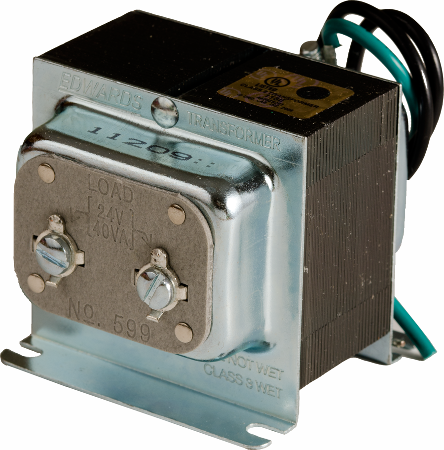
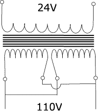
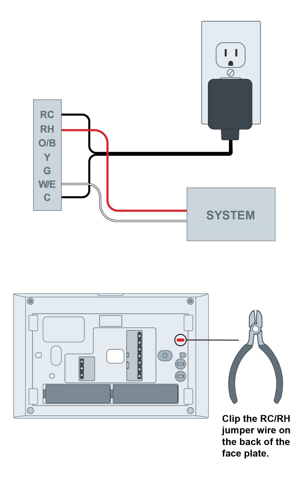
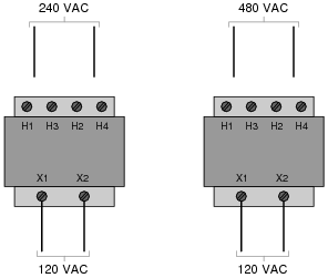
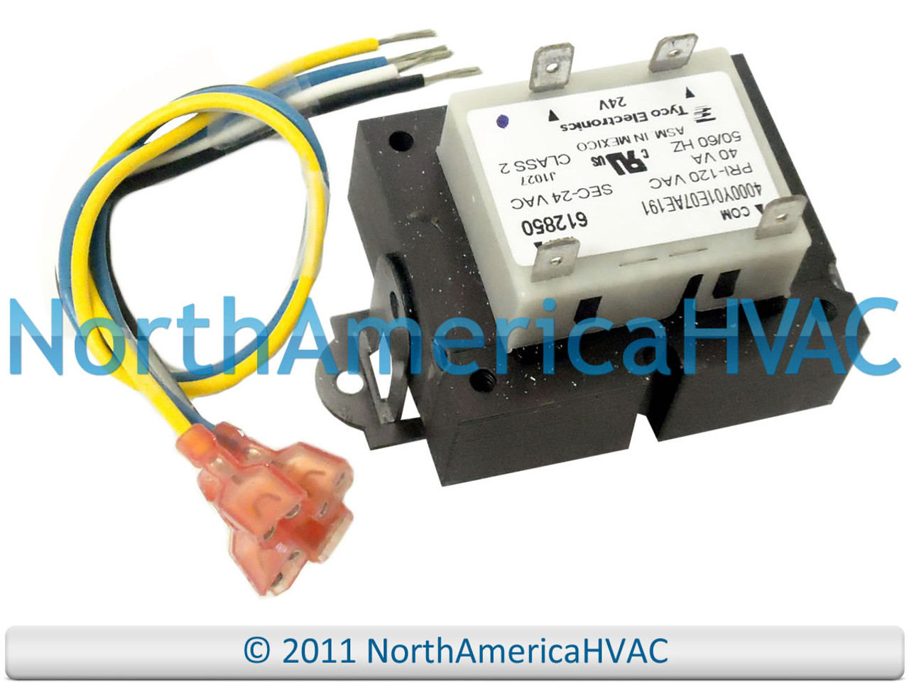
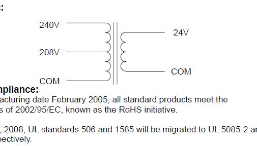
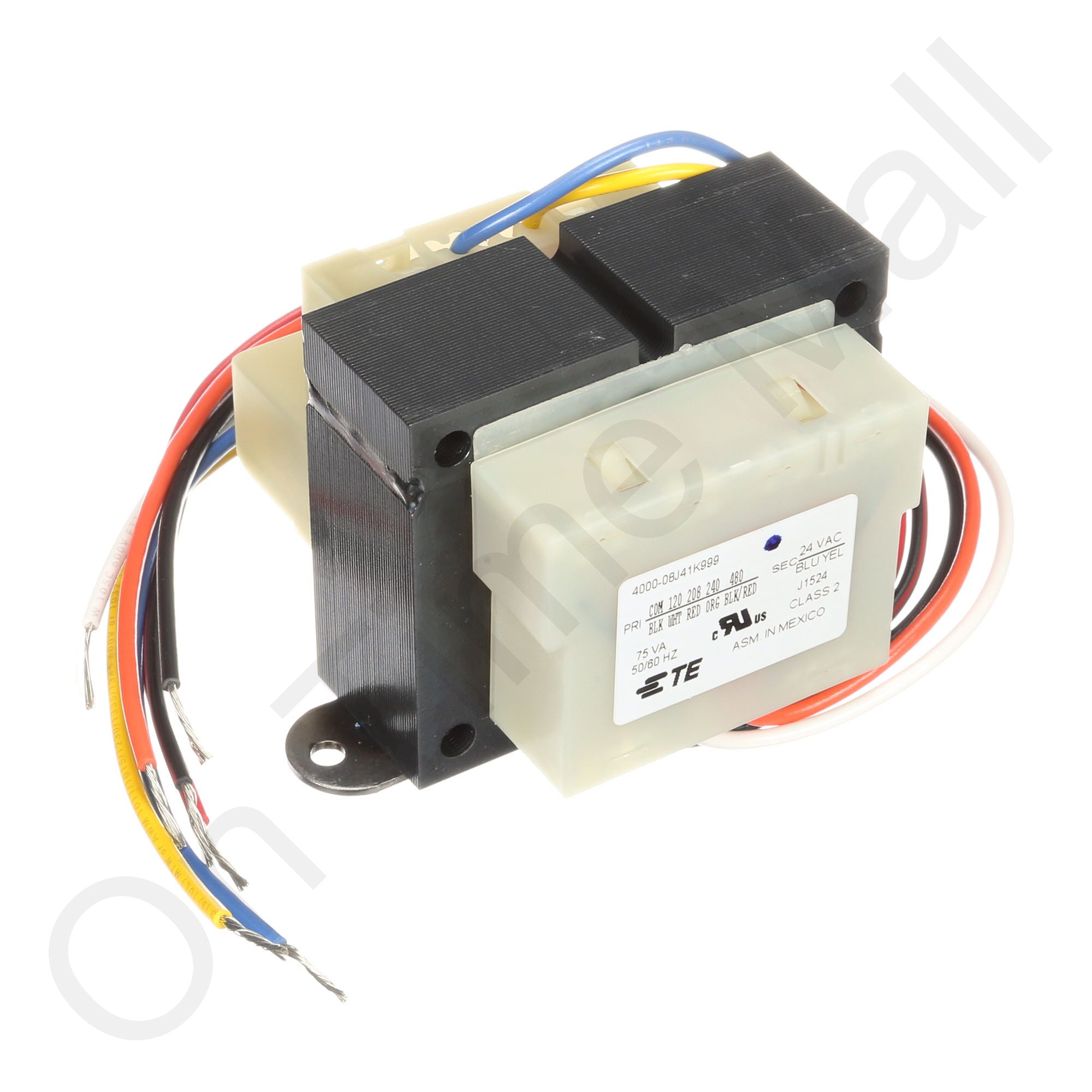
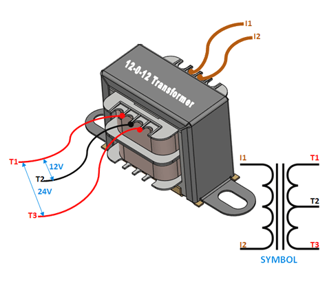
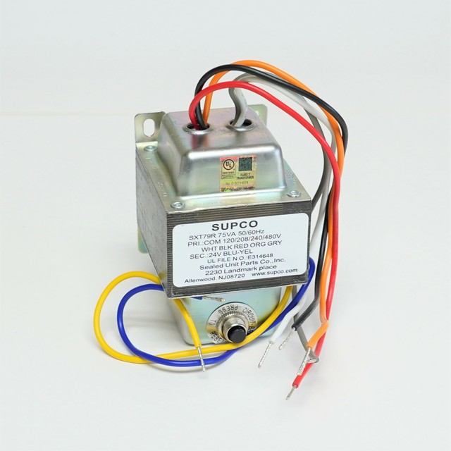
42 120 to 24 volt transformer wiring diagram
PDF Aprilaire Humidifier Wiring Diagrams - Alpine Home Air 24 Vo lt 120V Hot To 120V Power This configuration allows the humidifier to run whenever there is a call for heat. Make sure the "HUM" terminal is 24 volts and not 120 volts. If the terminal is 120 volts, a 24 volt transformer will have to be installed. (Refer to your furnace's manual for voltage.) Diagram #3 Aprilaire Automatic ... 120 Volt Motor Wiring Diagram - The Wiring 480 volt to 120 volt transformer wiring diagram - 480 Volt To 120 Transformer 480v Step Down Up 208 Isolation 240v 208v For 480V 120V Wiring Diagram; View Profile View Forum Posts Diamond Join Date Dec 2002 Location Monterey Bay, California Posts 10,260 Post Thanks / Like Likes (Given) 28 Likes (Received).
220 Volt Plug Receptacles Configurations - AskmeDIY 03.12.2021 · Ok, so let’s talk about the types of outlets you’ll find in your house. For the most part, you are going to see 120 volts, 15 amp, and 20 amp. And 220 2 wire, 3 wire, and four wire types. Please remember not all 220-volt outlets use a neutral (white) wire. To give you a general idea, let’s say you just bought an air compressor from Home ...

120 to 24 volt transformer wiring diagram
PDF Acme Electric - Dry-Type Distribution Transformers ... ACME ELECTRIC † MILWAUKEE, WI † 800.334.5214 † acmepowerdist.com 157 GENERAL ELECTRICAL CONNECTION DIAGRAMSACME® TRANSFORMER™ WIRING DIAGRAMS PRIMARY: 240 Volts Delta SECONDARY: 208Y/120 Volts TAPS: 2, 5% BNFC X1 H1 X2 X3 H2 H3 X0 3 2 1 3 2 1 3 2 1 Connect Connect Primary Primary Inter- Secondary PDF Wiring Diagrams - AutomationDirect If you have any questions regarding these wiring diagrams or are having any difficulty correctly installing our transformers, please contact HPS customer service or technical support in the U.S. at 1-866-705-4684 or in Canada at 1-888-798-8882. HPS Imperator tm Industrial Control Transformer Wiring Diagrams Issue Date: October 2007 rev4 Page 1 of 9 120 To 24 Volt Transformer Wiring Diagram - Studying Diagrams Oct 21, 2021 · 120 to 24 volt transformer wiring diagram. However it doesnt mean connection between the cables. The most common application for a 24 VAC transformer is to activate. There will be principal lines which are represented by L1 L2 L3. 480 To 120240 Transformer Wiring.
120 to 24 volt transformer wiring diagram. PDF Connecting a multi-tap transformer for 24 volt output. 2. Check this wiring diagram against the wiring diagram supplied with the transformer. The color of the wires may be different. 3. The general rule is that the more winding that is connected on the primary, the lower the secondary voltage. Examples: a) 120 volts connected to the Black & Red wires provides only 12 volts at the secondary. VOLVO S40 WIRING DIAGRAM Pdf Download - ManualsLib View and Download Volvo S40 wiring diagram online. 2006. S40 automobile pdf manual download. Also for: V50, 2006 s40, 2006 v50. 120 Volt Switch Wiring - The Wiring 480 volt to 120 volt transformer wiring diagram - 480 Volt To 120 Transformer 480v Step Down Up 208 Isolation 240v 208v For 480V 120V Wiring Diagram; With this wiring, both the black and white wires are used to carry 120 volts each and the white wire is wrapped with electrical tape to label it hot. 24 Volt Transformer Wiring Diagram - Cadician's Blog 24 Volt Transformer Wiring Diagram - Trusted Wiring Diagram Online - 24 Volt Transformer Wiring Diagram. Wiring Diagram arrives with several easy to adhere to Wiring Diagram Instructions. It really is intended to aid all the typical user in building a suitable program. These instructions will likely be easy to comprehend and apply.
PDF 120/208/240 to 24VAC Transformer (Supplied) 3. Connect the wires above to the relay per the wiring diagram, Figure 1. 4. Connect the wires from the HALO-LED to the supplied transformer per Figure 1. 5. Connect AHU Line 2 to the supplied transformer according to the unit voltage. HALO-LED Condenser Common/ TStat Common Yellow wire from AHU Condenser Contactor-Power 120/208/240 to 24VAC ... 480 To 120/240 Transformer Wiring - Wiring Diagram Pictures a volt primary transformer with a volt secondary is operated at volts, regardless of whether the source is three phase 3-wire or three phase 4-wire. .. example: A 10 kVA transformer, / volt secondary is to service an 8 kVA . Single Phase Transformer Primary and Secondary wiring. LV (600V) Dry-Type Transformers - Federal Pacific Single-Phase Transformer Quick Reference Guide Single Phase Encapsulated Transformers Part Number = Family [-KVA] [-N/T] (P2X only for taps) Conductor Temp Rise (Celsius) Electrostatic Shield Primary/Secondary Family KVA Available Taps Available CU 115°C N 120x240V - 120/240V 208V - 120/240V 277V - 120/240V P1XGF21 P20GF21 P27GF21 1, 1.5, … 120 Volt To 24 Ac Transformer Wiring Diagram - Wiring View ... Oct 06, 2021 · 120 Volt To 24 Ac Transformer Wiring Diagram. 28 amp relay central vacuum low voltage transformers how to wire a multi tap transformer functional devices inc 40va primary 120v 208v 240v volt 24v secondary hvac furnace com 12 0 centre tapped wiring specifications use it control circuits for systems quality tips 101 24 packard pf42440 592 edwards ...
PDF Buck-boost Transformer Installation Sheet If you are using this unit as an isolation transformer with a primary of 120 or 240 or 480 volts and the secondary of 12/24, 16/32, or 24/48 (depending on the model) use the wiring diagram located on the inside of the cover to the wiring compartment. If you are using this unit as an auto transformer to buck (lower) or boost (raise) the voltage ... Zone Valve Wiring Manuals Installation & Instructions ... We see 24-volts through the zone controllers and transformer but Zero voltage on the zone valve end switch wires that go to the thermostat TT terminals on the master or primary control. Reader Question: how many zone valves can be connected to a single thermostat? 3/5/2014 TEJ said: how many zonal valves for floor heating can be connected to one room thermostat. This … PF42440 Packard 24V universal transformer 120-208-240V ... 120 volt instructions: Connect white and black wires to 120V input. Connect red and green wires to 24V output. 208 volt instructions: Connect white and red wires to 208V input. Connect red and green wires to 24V output. 240 volt instructions: Connect white and orange wires to 240V input. Connect red and green wires to 24V output. Utilitech Doorbell Transformer Wiring Diagram - U Wiring Replacing wired doorbell. Utilitech doorbell transformer wiring diagram. 20 Off Your Lowes Advantage Card Purchase. 120 Volt to 24 Volt Transformer Wiring Diagram wiring diagram is a simplified okay pictorial representation of an electrical circuit.One-time 20 off discount is not automatic. It can be hooked up to use.
Amazon.com: 120 to 24 volt transformer 24V LED Power Supply - Lustaled Waterproof IP67 15W 24 Volt DC Transformer 120V AC to 24V DC Constant Voltage Outdoor LED Driver Converter for LED Strip Lights CCTV Camera Security System (2-Pack) 4.3 out of 5 stars. 180. $15.99.
120 to 24 transformer wiring | Electronics Forum (Circuits ... For 120 volt primary you would parallel the windings tying 1&3 and 2&4 together and apply 120 volts AC. For 240 volt operation the primaries go in series and you would tie 2&3 together and apply 240 volts AC to 1&4. The secondary should be as drawn. If you plan to use this you should understand it and be careful working around mains power.
PDF Electrical Connection Diagrams Acme Transformer Design Figures ACME ELECTRIC U MILWAUKEE, WI U 800.334.5214 U acmetransformer.com 125 GENERALGENERAL ELECTRICAL CONNECTION DIAGRAMSACME® TRANSFORMER™ WIRING DIAGRAMS PRIMARY: 240 Volts Delta SECONDARY: 208Y/120 Volts TAPS: 2, 5% BNFC X1 H1 X2 X3 H2 H3 X0 3 2 1 3 2 1 3 2 1 ConnectConnect Primary Primary Inter- Secondary
480v 3 Phase To 120 240v Transformer Wiring Diagram ... Control circuit wiring of cpts. Collection of 480 volt to 120 volt transformer wiring diagram. 480v to 240v transformer wiring diagram Youll need an extensive skilled and easy to know Wiring Diagram. It reveals the elements of the circuit as streamlined shapes as well as the power and also signal connections between the gadgets.
How do you wire a Packard transformer? - AskingLot.com Packard PF42440 transformer 120-208-240V 40VA 24V 120 volt instructions: Connect white and black wires to 120V input. Connect red and green wires to 24V output. 208 volt instructions: Connect white and red wires to 208V input. Connect red and green wires to 24V output. 240 volt instructions: Connect white and orange wires to 240V input.
240 To 24 Volt Transformer Wiring Diagram - Wiring Sample Collection of 24 volt transformer wiring diagram. These instructions will likely be easy to comprehend and apply. The lower voltage is sent to the push button to engage the chime mechanism. 240 volts delta secondary. If you are using this unit as an isolation transformer with a primary of 120 or 240 or 480 volts and the secondary of 12 24 16 32 ...
120 To 24 Volt Transformer Wiring Diagram - wek.app Mar 29, 2021 · 120 to 24 volt transformer wiring diagram. 2 illustrates the phasor diagram of the output voltages for a split-phase transformer. It plugs into a 230 volt receptacle and provides 120 volt power. Load voltage or secondary voltage is the voltage needed to operate the load. 15 1 minute read. 24V C WIRE POWER ADAPTER.
480v To 120v Control Transformer Wiring Diagram - easywiring Variety of step down transformer 480v to 120v wiring diagram. 480 to 120 240 transformer wiring 06 04 2019 06 04 2019 2 comments on 480 to 120 240 transformer wiring a volt primary transformer with a volt secondary is operated at volts regardless of whether the source is three phase 3 wire or three phase 4 wire. 240 x 480 secondary.

GE 9T51B0108 Type QB Dry Encapsulated Buck Boost Transformer, 120/240 VAC Primary, 12/24 VAC Secondary, 0.5 kVA, 60 Hz
with Equipment Interface Module Installation Guide - Honeywell Common wire from 24 VAC transformer. C Common wire from 24 VAC transformer. R* Power wire from 24 VAC transformer. R Power wire from 24 VAC transformer. RH* Heating power. RH Heating power. RC* Cooling power. RC Cooling power. W Heat Stage 1 O/B Changeover valve for heat pumps. W2 Heat Stage 2 AUX 1 Backup Heat Stage 1/Emergency Heat Stage 1 W3 …
24 Volt Transformer Wiring Diagram - Wirings Diagram 24 Volt Transformer Wiring Diagram - 120 volt to 24 volt ac transformer wiring diagram, 208 to 24 volt transformer wiring diagram, 24 volt furnace transformer wiring diagram, Every electric structure is composed of various distinct parts. Each part should be set and connected with other parts in specific manner. Otherwise, the arrangement will not work as it should be.
120 To 24 Volt Transformer Wiring Diagram - easywiring Apr 12, 2021 · 120 to 24 volt transformer wiring diagram. A 10 kva transformer volt secondary is to service an 8 kva. The color of the wires may be different. A 120 volts connected to the black red wires provides only 12 volts at the secondary. A 24 vac volt alternating current transformer is a step down type of transformer.
Solar Panel Wiring Diagram and Installation Tutorials I am not sure why you said 2pcs of 120ah12V battries in series. He needs batteres to supply the 1500w loads for 12hours at night. Basically that is 1500w * 12 = 18000wh. dividing by 50% depth of discharge as you choose flooded, that is 18000/0.5=36000wh or divde by 0.8 if for AGM batteries, that is 18000/0.8 = 22500wh.
480v To 120v Control Transformer Wiring Diagram 480v To 120v Control Transformer Wiring Diagram. Why use a Control Power Transformer? The schematic symbol for the transformer is represented by two groups the main motor circuit operates at V, while the control circuit is at V. Control Circuit Wiring of CPTs. I have a control transformer which has v 3 phase primaryv single phase secondary.
480 Volt to 120 Volt Transformer Wiring Diagram Sample ... Name: 480 volt to 120 volt transformer wiring diagram - 480 Volt To 120 Transformer 480v Step Down Up 208 Isolation 240v 208v For 480V 120V Wiring Diagram File Type: JPG Source: teenwolfonline.org
Thermostat Terminal Designations HVAC Wiring Quality 101 The C-terminal is the 24 volt common (as opposed to hot). This terminal is necessary to power thermostat as the thermostat needs a source of power to operate. This terminal is kind of like the neutral side of a 120-volt circuit. A basic circuit needs a source, a path, and a load. In this case, the source is the transformer, the load is the ...
24 Volt Transformer Wiring Diagram - Wiring Diagram 24 Volt Transformer Wiring Diagram - Trusted Wiring Diagram Online - 24 Volt Transformer Wiring Diagram. Wiring Diagram arrives with several easy to adhere to Wiring Diagram Instructions. It really is intended to aid all the typical user in building a suitable program. These instructions will likely be easy to comprehend and apply.
120 To 24 Volt Transformer Wiring Diagram - Wiring View ... 120 To 24 Volt Transformer Wiring Diagram. By Margaret Byrd | January 30, 2022. 0 Comment. 28 amp relay central vacuum 120v 24v transformer for brooders hog slat honeywell home 24 volt at72d the 4 1611453 7 productsunlimited te connectivity 40va 100va primary 208v 240v 480v secondary hvac furnace multi tap com how to wire a functional devices ...
METERING INSTALLATION REQUIREMENTS - Native Americans in ... 120/240 Volt UG Service Pull Section Sealable Acceptable Customer Equipment Location 3/4" 2 1/2" 1-1/4" * Current Transformer Dimensions *These are general dimensions of currrent transformers available with existing demand controllers. There may be new units in the future that will not conform to these dimensions.
How to Wire a 24V Transformer - Hunker A 24 VAC (volt alternating current) transformer is a step-down type of transformer. The device typically converts 120 VAC to a lower voltage for use in push buttons. The most common application for a 24 VAC transformer is to activate a doorbell chime. The lower voltage is sent to the push button to engage the chime mechanism.
120 To 24 Volt Transformer Wiring Diagram - DUNAJEC Jan 17, 2022 · Sep 25 2011. 120 Volt to 24 Volt Transformer Wiring Diagram wiring diagram is a simplified okay pictorial representation of an electrical circuit. Pin On Elektronika . 240 Volts Delta SECONDARY. 120 to 24 volt transformer wiring diagram. Each part should be set and connected with other parts in specific manner. 24 Volt Transformer Wiring ...
120 To 24 Volt Transformer Wiring Diagram - Studying Diagrams Oct 21, 2021 · 120 to 24 volt transformer wiring diagram. However it doesnt mean connection between the cables. The most common application for a 24 VAC transformer is to activate. There will be principal lines which are represented by L1 L2 L3. 480 To 120240 Transformer Wiring.
PDF Wiring Diagrams - AutomationDirect If you have any questions regarding these wiring diagrams or are having any difficulty correctly installing our transformers, please contact HPS customer service or technical support in the U.S. at 1-866-705-4684 or in Canada at 1-888-798-8882. HPS Imperator tm Industrial Control Transformer Wiring Diagrams Issue Date: October 2007 rev4 Page 1 of 9
PDF Acme Electric - Dry-Type Distribution Transformers ... ACME ELECTRIC † MILWAUKEE, WI † 800.334.5214 † acmepowerdist.com 157 GENERAL ELECTRICAL CONNECTION DIAGRAMSACME® TRANSFORMER™ WIRING DIAGRAMS PRIMARY: 240 Volts Delta SECONDARY: 208Y/120 Volts TAPS: 2, 5% BNFC X1 H1 X2 X3 H2 H3 X0 3 2 1 3 2 1 3 2 1 Connect Connect Primary Primary Inter- Secondary















0 Response to "42 120 to 24 volt transformer wiring diagram"
Post a Comment