40 buffer tank piping diagram
Can I have a tank fed water heater in line with a tankless ... Hot water tank heaters have a significantly higher flow rate than tankless heaters and so for a given piping system they will deliver hot water sooner after turn on, but then of course with continuous delivery the tank will be depleted of hot water and you will get none until the tank "recovers". You don't have an ideal system with a tankless heater in the basement, but … Benchmark 5000 and 6000 - AERCO Measuring only 79.8" high x 35" wide x 89.3" deep, the Benchmark 5000 and 6000 (BMK5000/6000) commercial condensing boilers feature up to 15:1 turndown for energy efficiency, Low NOx emissions, and high reliability in an unmatched compact footprint that is up to half the size of any other five/six million BTU/hr boiler on the market.
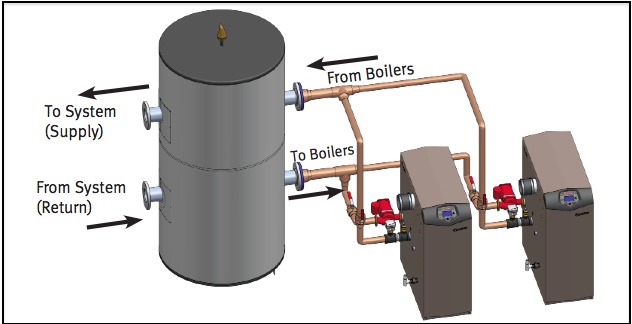
PDF Buffer Tank Piping Supplement - PB Heat The buffer tank should be sized in accordance with the tank manufacturer's instructions. B. Piping Buffer Tank Piping using 4 tank connections: For buffer tanks with four system connections, Figure 1.1 shows the recommended piping. Notice that the diagram shows a system sensor on the system supply pipe.
Buffer tank piping diagram
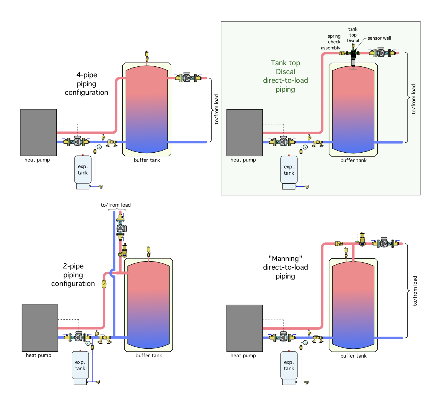
PDF HYDRONIC BUFFER TANKS - Heat-flo is available for alternate piping configurations. When configured and piped correctly, Heat-flo hydronic buffer tanks can serve as both a thermal buffer and a hydraulic separator - allowing the heating or cooling source to be hydraulically decoupled from the distribution system. HYDRONIC BUFFER TANKS Different ways to pipe a thermal storage tank | 2016-03-22 ... Rethinking tank piping. The piping shown in Figures 1, 2 and 3 all involve four principal piping connections on the sides of the thermal storage tank, two into the upper portion and two into the lower portion. Although these principal connections can function well, they are not the only way to connect a thermal storage tank into the system. Piping layouts to avoid in hydronic systems - HPAC Magazine Related: When to use a three-pipe buffer tank configuration. The designer proceeds to sketch out the loop, and puts in a primary loop circulator. Next it is time to add some load circuits. This is where the designer's memory flashes back to neatly aligned zone circulators all lined up on a wall. With that in mind, the designer connects the ...
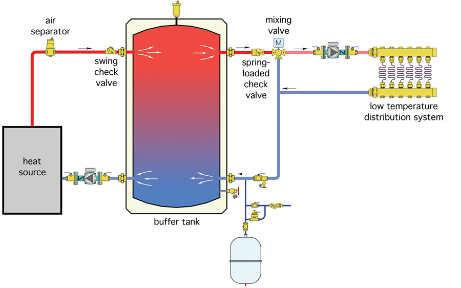
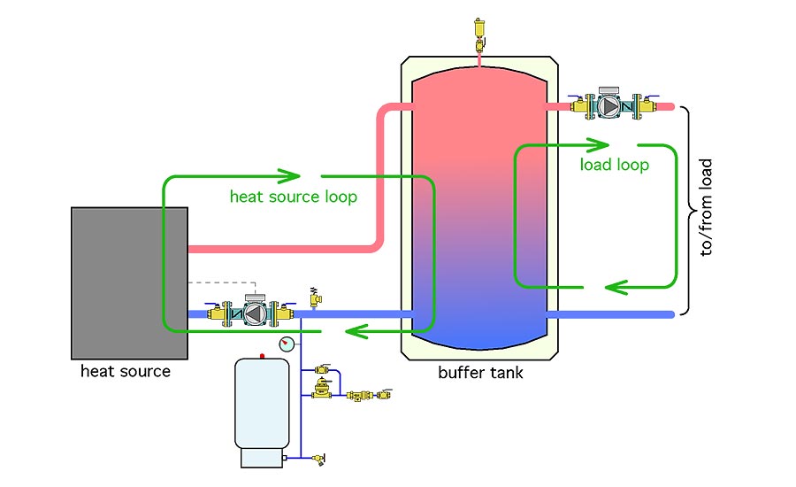
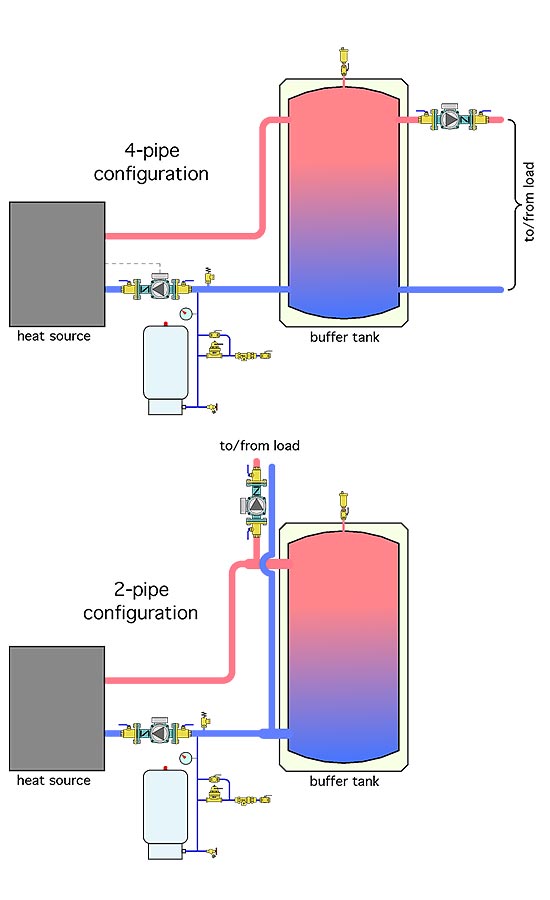
Buffer tank piping diagram. Buffer Tanks - Amtrol Amtrol ASME Buffer Tanks add capacity to non-potable, closed systems to help reduce cycling, improve temperature control and provide more consistent system operation. Available for chilled water and hot water applications. All Amtrol Buffer Tanks are made in the USA at our ISO 9001:2015 registered facilities. The finer points of applying a 2-pipe buffer tank | 2017 ... The advantage of 2-pipe tanks. A 2-pipe buffer tank places the piping leading to and from the heating load between the heat source and the buffer tank. If the load is operating at the same time as the heat source, which is common, the flow rate passing into the buffer tank is the difference between the heat source flow rate, and the load flow rate. Residential and Commercial Piping Diagrams | A. O. Smith Access piping diagrams for your commercial or residential water heater. For more product literature, including specs and parts lists, visit Hotwater.com. Chilled water buffer Tanks - HVAC/R engineering - Eng-Tips My colleague handling the layout of the project was planning to pipe the buffer tanks in series with either - Solution 1: tank 1 having top inlet and bottom outlet piped to tank 2 bottom inlet, then from tank 2 top outlet to tank 3 top inlet and from tank 3 bottom outlet to tank 4 bottom inlet
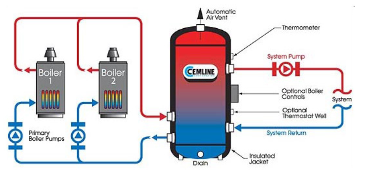
PDF BASIC HYDRONIC SYSTEM DESIGN - ctashrae.org 4 DECOUPLERS Closely Spaced Tees Buffer TankHydraulic Separator (depends) DECOUPLER Head = 0' PRIMARY FLOW TERMINAL UNIT Head = 10' - 20' CLOSELY SPACED TEES Distance Between Tees as Short as Possible (Tee to Tee). Pressure Drop Between Tees Will Determine Flow to Terminal Unit WATER ALWAYS FOLLOWS PATH OF LEAST RESISTANCE 5 HYDRAULIC SEPARATORS piping buffer tank — Heating Help: The Wall piping buffer tank Jim_70 Member Posts: 10 November 2005 temp setting is for an operating temp of 180 or so. In both the inlet and outlet, there are temp sensors that I assume tell the burner when to fire and also when to shut off at the limit. The boiler tends to fire when the temp gauge is at 150. It is a 300,000 unit (output is about 245,000). Chiller Application Guide - Daikin Applied Piping Basics The chilled water piping is usually a closed loop. A closed loop only interacts with the atmosphere at the expansion tank. Figure 3 shows a simple closed loop system. The static pressure created by the change in elevation is equal on both sides of the pump because the system is closed. In a closed loop, On-Demand Heater With Buffer Tank Plumbing Diagram ... On-Demand Heater With Buffer Tank This diagram shows an instantaneous water heater system with a buffer tank and recirculation loop. The expansion tank is typically installed on the cold water inlet but can be installed on the hot water supply after the water heater. The use of the buffer tank is to assist when a large instantaneous demand occurs.
Benchmark 2500 and 3000 - AERCO Installation and Piping Drawings ACS - DHW Priority (ACS Only) Benchmark, SmartPlate, Buffer Tank Applications (SD-A-916) (.dwg) ACS - DHW Priority (ACS Only) Benchmark, SmartPlate, Buffer Tank Applications (SD-A-916) (.pdf) Chilled Water System: Components, Diagrams & Applications ... The chilled water loop is a closed loop piping system. The amount of water inside the chilled water loop does not increase or decrease. Conversely, the condenser water loop is an open piping system. Hence, the make-up water tank is used to refill water losses due to evaporation at the cooling tower. PDF I. Piping Diagrams 13. Wire the tank or system/pipe sensor connected to the DHW sensor terminals on the follower boiler addressed as #1. 14. The system/pipe sensor must be placed on common piping to the tank, as close to the tank as possible. 15. The system/pipe sensor is wired to the system sensor terminals on the master boiler. PDF Multiple Boiler Piping Diagram Full Flow - Lochinvar, LLC TANK AIR SEPERATOR DRAIN PORT (TYPICAL) SYSTEM CIRCULATOR TO SYSTEM MAKE UP WATER BACK FLOW PREVENTER PRESSURE REDUCING VALVE PRESSURE GAUGE . Title: Near Boiler Piping Author: David A. George Created Date:
One side or the other - HPAC Magazine
(PDF) GAPS Guidelines GAP.2.5.2 A ... - Academia.edu PROCESS PIPING DESIGN HANDBOOK - VOLUME 2 [Advanced Piping Design] By Muhammad Nasrullah. Hazard identification, Risk assessment & consequence modelling of pool fire of bulk stored crude in tank Farm. By Mohasin Rasheed. Exploration & Production Design of Field Facilities GS EP SAF 021 Layout Main Instructor for Derogation: ECI (Design of Field …
Heat Pump Plus - HPAC Magazine
Homemade Hydraulic Ram Pump for Livestock Water | Land ... The air chamber (#14–16) acts like a pressure tank for a well, using compressible air captured in the tank to buffer shock waves and provide a steady outlet pressure. The air initially captured in this air chamber, however, will be absorbed by the water flowing through the pump over time. When this happens there will be a much more pronounced shock to the pump and piping …

Buff up your knowledge of buffer tanks- Kensa Heat Pumps
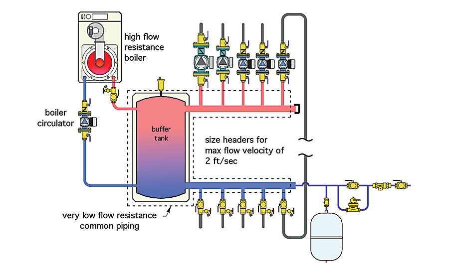
PDF Beyond Primary / Secondary Piping - Caleffi Pipe size of hydraulic separato r 1" 1.25" 1.5" 2" 2.5" 3" 4" 6" Max flow rate (GPM) 11 18 26 40 80 124 247 485 The header piping connecting to the distribution side of the Hydro Separator should be sized for a flow of 4 feet per second or less under maximum flow rate conditions.
John Siegenthaler: Due diligence | 2020-09-22 | Plumbing ...
Thermal Energy Storage - Overview and basic principles 17.08.2020 · A buffer tank can be used daily to reduce the peak power of heat generators in DHC systems. ... Rock caverns can also be used as short-term displacement storages. The piping network itself is other form of short-term storage, used to smoothen constrains between heat load and heat generation in district heating systems. Other applications of TES are small …

HeatSpring Magazine – 2-Pipe Versus 4-Pipe Buffer Tank ...
When to use a three-pipe buffer tank configuration - HPAC ... A thermal storage tank, left undisturbed, will naturally stratify. The temperature range from top to bottom will depend on several factors, including: • The height to diameter ratio of the tank • The thermal conductivity of the tank walls • The insulation used on the tank Conductive/convective heat loss through piping connected to the tank
Cemline Corporation - Chilled Water Buffer Tanks
Heating diagrams for boilers, buffer tanks and solar ... All system components from Solarbayer, including a wood gasifying boiler, stratification buffer tanks, solar DHW tank and a thermal solar system with flat plate collectors. Heating diagrams A collection of hydraulic drawings of established installation

View simple piping and wiring drawings for residential ...
PDF CHILLED WATER BUFFER TANKS - Amtrol A: Buffer tanks provide extra water volume in a closed chilled water system. Q:Are buffer tanks used in every chilled water system? A: No. Some systems have an adequate volume of water in them so the extra storage provided by the buffer tank is not required. Q: How do they work? A: The added capacity, provided by the tank, reduces

All About Chilled Water Buffer Tanks! | American Wheatley
Multi-Purpose Tanks | Multi-Purpose Tanks (MPT) Meets ASME Code Section VIII, Division 1 Taco's MPT style Multi-Purpose Tanks product line offering incorporates the features of Taco's Buffer tank, 5900 and Air/Dirt separator product line within a single product. This product line offers tank sizes ranging between 50 and 1050 gallons.
Chilled Water Buffer Tanks
HeatSpring Magazine - 2-Pipe Versus 4-Pipe Buffer Tank ... If the buffer tanks have the four principal piping connections shown in Figures 1 through 3, it is possible join two or three of them together in a "close coupled" arrangement as shown in Figure 6. FIGURE 6 This piping allows the two buffer tanks to maintain flow dynamics very similar to the single "2-pipe" buffer tank shown in figures 4 and 5.
Buffer Tank Piping Modifications: Dual to Single Direction ...
Condensing Boiler Piping Design - Hot Water Buffer Tanks ... Condensing Boiler Piping Design - Hot Water Buffer Tanks. Condensing Boiler Piping Design - Hot Water Buffer Tanks.
Air to Water heat pump pipe layout — Heating Help: The Wall
Piping Diagram - Cemline 2 USG's Piped in Parallel - PDF or DWG USG Steam Fired Piped to a CBO - PDF or DWG 2 - USG's Piped in Parallel to 1 CBO - PDF or DWG Instantaneous Water Heaters (SEH) Semi-Instantaneous Water Heaters (SSH) Storage Type Water Heaters (SWH) Storage Plate Water Heaters (SPH) Condensing Companion Water Heaters (CCH) Brazed Plate Water Heaters (BPH)
A Buffer tank issue? | Terry Love Plumbing Advice & Remodel ...
Buffer Tank Piping Diagram — Heating Help: The Wall Buffer Tank Piping Diagram. Steve_210 Member Posts: 615. August 2018. in THE MAIN WALL. Looking for a piping digram for the use of a buffer tank. We've installed many boilers with indirects, but never had to use a buffer tank before. Had a complaint of short cycling during the winter time. There are a lot of micro zones and house is very well ...
Washington - Heat Exchanger for Spa | GeoExchange® Forum
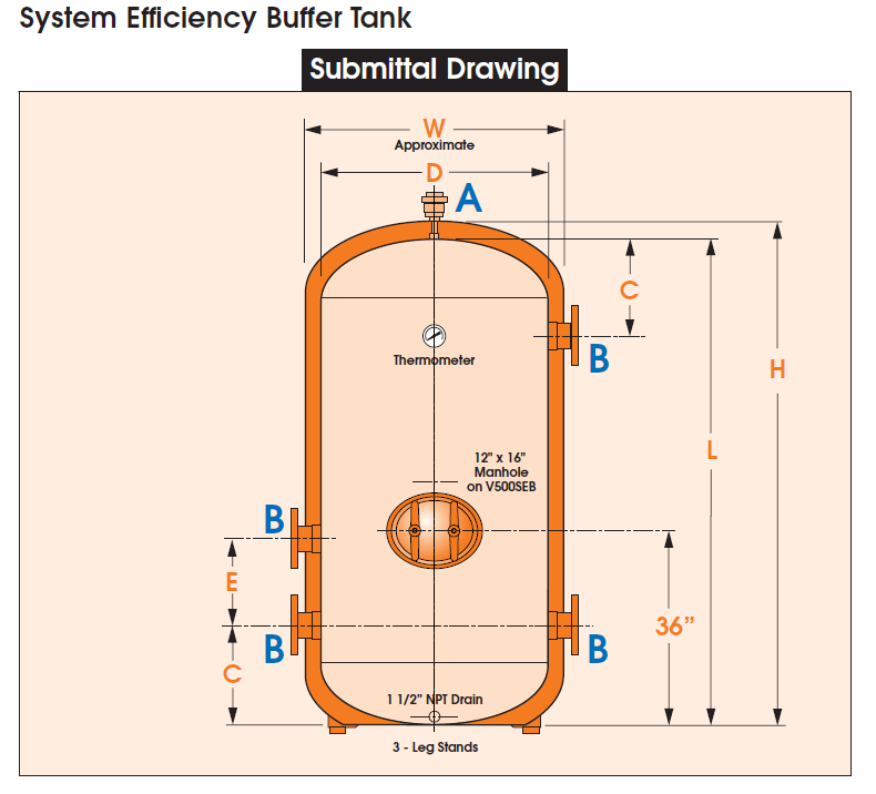
Hydronic Heating Buffer Tanks Part 2 - Sizing | R.L. Deppmann 1360 gallons minus the system volume of 1000 gallons leave the required tank size at 360 gallons minimum. Use a Cemline model V500SEB. Example 2: The volume used in the expansion tank calculation with no safety factor is 1000 gallons. I have a load of 6,000,000 BTUH in my primary secondary system.
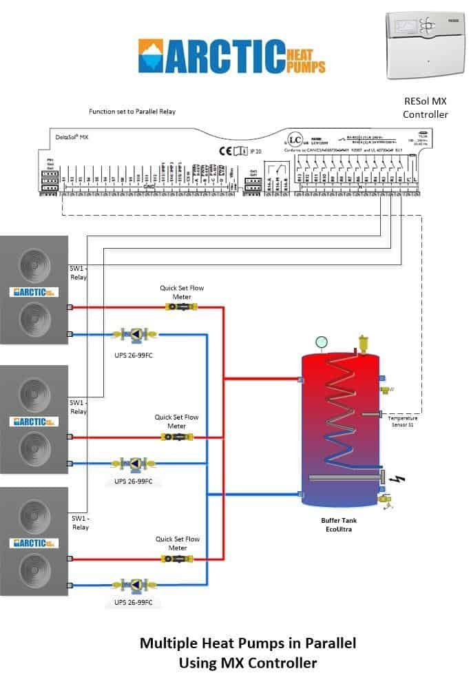
Multiple Heat Pumps for Larger Home or Businesses | Articles
Chilled Water Buffer Tanks (CWB) - Cemline CEMLINE® Chilled Water Buffer Tanks (CWB) are designed to be used with chillers which do not have water volumes of sufficient size in relation to the chiller. The insufficiently sized systems do not have enough buffer capacity for the chilled water causing poor temperature control, erratic system operation and excessive compressor cycling.
Hydronic Heating Buffer Tanks Part 2 - Sizing | R.L. Deppmann
Buffer Tanks for Cold and Hot Water Systems | Wessels Company Wessels ASME Hot water Buffer Tanks (HBT) are designed for use with today's high efficiency systems that incorporate small, modular low-mass boilers. A properly sized Wessels Hot Water Buffer Tank adds necessary thermal mass to the system to dampen fast transitions and minimize boiler cycling that occurs during zero or low domestic load conditions.

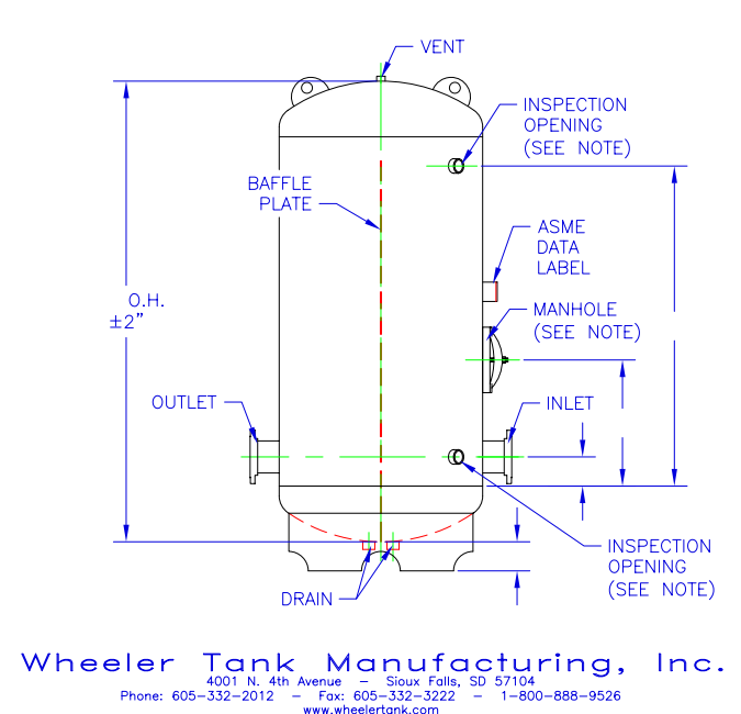
ASME-Chilled-Water-Buffer-Tanks-Dimension-Diagram - Elbi of ...
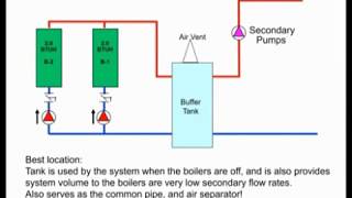
Impovements to ERGOMAX & Buffer Tanks Buffer Tanks We are now manufacturing two buffer tanks, models BT26 & BT 48 (see the suggested piping diagram and specifications below). In those instances where an ERGOMAX heat exchanger is not used, but the boiler short cycles, a buffer tank can be used to eliminate the short cycling and save fuel.
Hydronic Heating Buffer Tanks Part 2 - Sizing | R.L. Deppmann
Piping layouts to avoid in hydronic systems - HPAC Magazine Related: When to use a three-pipe buffer tank configuration. The designer proceeds to sketch out the loop, and puts in a primary loop circulator. Next it is time to add some load circuits. This is where the designer's memory flashes back to neatly aligned zone circulators all lined up on a wall. With that in mind, the designer connects the ...

Heating diagrams for boilers, buffer tanks and solar collectors
Different ways to pipe a thermal storage tank | 2016-03-22 ... Rethinking tank piping. The piping shown in Figures 1, 2 and 3 all involve four principal piping connections on the sides of the thermal storage tank, two into the upper portion and two into the lower portion. Although these principal connections can function well, they are not the only way to connect a thermal storage tank into the system.

Hydraulic Separator & Chilled Water Buffer Tanks | A. O. Smith
PDF HYDRONIC BUFFER TANKS - Heat-flo is available for alternate piping configurations. When configured and piped correctly, Heat-flo hydronic buffer tanks can serve as both a thermal buffer and a hydraulic separator - allowing the heating or cooling source to be hydraulically decoupled from the distribution system. HYDRONIC BUFFER TANKS

HeatSpring Magazine – 2-Pipe Versus 4-Pipe Buffer Tank ...

Hydronic Buffer Tanks - Vaughn

Buffer tanks | Terry Love Plumbing Advice & Remodel DIY ...
Condensing Boiler Plant Piping Design & Control Part 5: How ...

Schematic representation of the buffer tank with the ...

buffer tank piping — Heating Help: The Wall
.jpg)
Chilled Water HVAC
Installation and Service Manual
John Siegenthaler: Due diligence | 2020-09-22 | Plumbing ...
Chilled Water Buffer Tanks - Wheeler Tank Manufacturing

Should I Consider A Buffer Tank? — Heating Help: The Wall
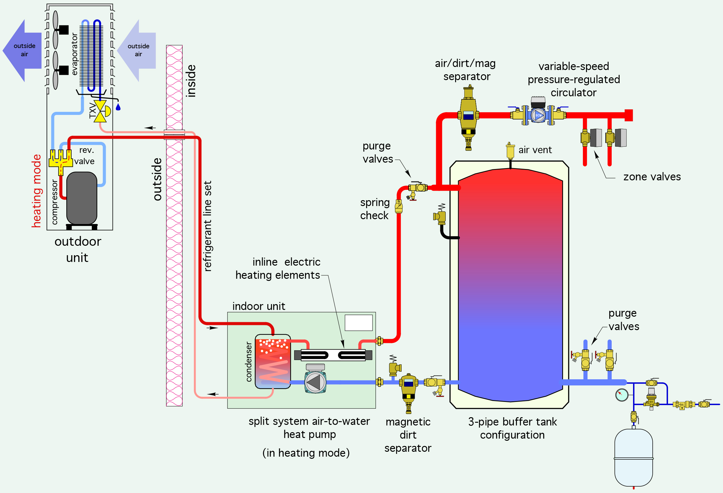
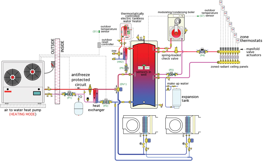
DESIGN DETAILS FOR AIR-TO-WATER HEAT PUMP | Caleffi Idronics

Typical P&ID arrangement for Storage Tanks - EnggCyclopedia

Condensing Boiler Piping Design - Hot Water Buffer Tanks
INS70069 Rev D.indd

Hydronic Tips: Piping Multiple Buffer Tanks
Condensing Boiler Piping Design - Hot Water Buffer Tanks ...

LoLiMoT based MPC for air handling units in HVAC systems ...
Peerless PureFire

10. Piping schematic of the buffer tanks (Crofoot, 2012 ...

Buffer tanks: Raypak | 2011-10-31 | Engineered Systems Magazine
0 Response to "40 buffer tank piping diagram"
Post a Comment