41 torque free body diagram
Torque Free Body Diagrams - Torque Project Free Body Diagrams for Torque situations usually include a weight for the object experiencing the torque, various or a single support force, and any other pushes or pulls that are acting to keep... PDF Chapter 12 Torque - University of Alabama • Determine the net torque when multiple forces act on a rigid object, using the superposition principle. • Identify and apply the conditions that cause an object ... Draw a free-body diagram for the rod of the figure below. Let the inertia of the rod be negligible compared to m 1 and m 2.
mechanical engineering - Determine the sign of torques for ... Free Body Diagrams: Note how the middle gear has no external torque acting on it. VIRTUAL POWER APPROACH. The second approach can be simpler to use, especially if the angular velocities are already known. First of all, a single algebraic equation relating the angular velocities of gears with external torques should be obtained.

Torque free body diagram
Calculating the torque angle in a free-body diagram ... I am primarily talking about this particular force diagram in the attachment of the OP. Nov 25, 2015 #6 sophiecentaur Science Advisor Gold Member 27,129 5,868 OK, so you have the force and you can easily calculate the perpendicular distance. Just drop a perpendicular from the pivot to the line of the string and find its length. FREE BODY DIAGRAMS. Introduction: A free body diagram is a picture of the forces which act on an object and is the first (and perhaps the most important) step in solving force problems. Purpose: The purpose of the free body diagram (FBD) is to help you identify and analyze the forces that act on a particular object or body. 1.5-3: Free body Diagrams with torque - YouTube Basic static equilibrium examples that emphasize drawing the free body diagram, choosing an axis, and evaluating torque without bothering to work out the num...
Torque free body diagram. RE: Shaft Mounted Gearbox Free Body Diagram - Mechanical ... Anyway, in summary your free body on the shaft should read. 200nM ccw, 200nm cw ,wihth an asterisk 96*9,8n upwards and 98,6 downwards with an asterisk. The asterisks are for the out-of plane forces. The bracket diagram is Ok except for the trivial kg to newton conversion. rb1957 (Aerospace) 18 Jan 11 14:54 How to Draw a Free Body Diagram: 10 Steps (with Pictures) A free-body diagram can be drawn very simply, with squares and arrows, or you can make it much more complex. The only requirement is that you or someone else looking at it should be able to understand what the diagram is telling. A free-body diagram (FBD) is a representation of a certain object showing all of the external forces that acts on it. PDF Internal Loads Normal Force and Torque Diagrams Draw a free-body diagram of the shaft on either side of the cut Use a static-equilibrium equation and the following sign convention to obtain the internal torque at the section Sign Convention Using the right-hand rule, the torque and angle of twist will be positive, provided the thumb is directed outward from the shaft when the PDF Mechanics lecture 7 Moment of a force, torque, equilibrium ... Free body diagrams • A free body diagram shows a body isolated from other bodies • All external forces and torques acting on it are shown To solve for a body in equilibrium: 1. Decide on the body of interest 2. Draw a diagram of the body isolated from other bodies in contact with it 3. Show all forces and torques acting on the body
Mathematical Models of Translating Mechanical Systems Free body diagram at θ 1: Free body diagram at θ 2: There are 4 torques acting: The external torque, τ a, clockwise. The torque due to K r.. If θ 1 increases (counterclockwise), K r causes a clockwise torque on J 1.; The resulting torque is K r ·θ 1, clockwise.; The torque due to B r1.. If θ 1 increases, the resulting torque on J 1 is B r1 ·ω 1 in the clockwise direction. Solved Problem 1: Torque and free-body diagrams In the ... Problem 1: Torque and free-body diagrams In the cases below, two equal and opposite forces are exerted on a long stick. The stick is free to rotate about a pivot at the center of the stick. F. F F, F Case 1 Case 2 Case 3 A. Rank the magnitude of the net torque in each case, from greatest to least. Forces and Torques in Muscles and Joints | Physics Figure 2. (a) good posture places the upper body's cg over the pivots in the hips, eliminating the need for muscle action to balance the body. (b) Poor posture requires exertion by the back muscles to counteract the clockwise torque produced around the pivot by the upper body's weight. 5.7 Drawing Free-Body Diagrams - General Physics Using ... Draw a free-body diagram for each block. Be sure to consider Newton's third law at the interface where the two blocks touch. Solution Significance →A 21 A → 21 is the action force of block 2 on block 1. →A 12 A → 12 is the reaction force of block 1 on block 2. We use these free-body diagrams in Applications of Newton's Laws. Example
Create Torque Diagram for Pulley Shaft Design TC-D - The torque at the section anywhere between C and D . Step-6: Draw the torque diagram: Plot the length of the shaft in X-axis and the torque values (calculated in step-3,4,5) at the different sections in Y-axis. Like below: The Final Torque Diagram. The torque values obtained from the torque diagram is used as input for the pulley shaft ... Free Body Diagram Involving Torque - Torque'n it up! This is a free body diagram of a yo-yo resting on a table. The force of gravity acting on the yo-yo (green arrow) is pulling downward on the yo-yo as it would on any object in ideal circumstances. The force of the table is the normal force (yellow arrow) reacting to the weight of the yo-yo on the table. How to Draw Free-Body Diagrams in Physics - dummies You can draw the components of your forces on your free-body diagram by using dashed lines (or next to it if your diagram is getting crowded). You can also use free-body diagrams to solve torque problems. When you're solving a torque problem, you also need to keep track of what part of the object the forces acts upon. PDF Forces and Free-Body Diagrams - pnhs.psd202.org Free-body diagrams are used to show the relative magnitude and direction of all forces acting on an object. This diagram shows four forces acting upon an object. There aren't always four forces. Problem 1 A book is at rest on a table top.
Torque and Rotational Motion Tutorial | Physics
How to Draw a Torque Diagram Without Equations - YouTube In this video, we solve a torque diagram without having to use equations. By simply looking at the external loadings, we can easily draw the internal torque...
Free body diagram - Wikipedia
PDF Chapter 5A. Torque - Saint Charles Preparatory School • Draw free-body diagram showing all forces, distances, and axis of rotation. • Extend lines of action for each force. • Calculate moment arms if necessary. • Calculate torques due to EACH individual force affixing proper sign. CCW (+) and CW (-). • Resultant torque is sum of individual torques. • • Read, draw, and label a rough ...

Mechanical Design - Free body Diagram of a Lead screw
PDF Free Body Diagrams and Fictitious Forces | Engineering ... This recitation reviews free body diagrams and covers a problem with a torsional spring pendulum followed by a second problem with a rolling pipe on an accelerating truck. Recitation 4 Notes: Torque and Angular Momentum, Pendulum with Torsional Spring, Rolling Pipe on Moving Truck (PDF)

Difference Between Torque and Force | Difference Between
mechanical engineering - How to draw a free body diagram ... What is the correct way to draw a free body diagram (FBD) for the following cylinder? Assume the cylinder and disc have been twisted to an angular deflection of θ. Further assume that we are drawing the FBD immediately after releasing the disc, so static equilibrium does not hold. I know there is a restorative force that grows as θ gets larger.

çadır Herşeyden dahafazla kaldır torque free body diagram ...
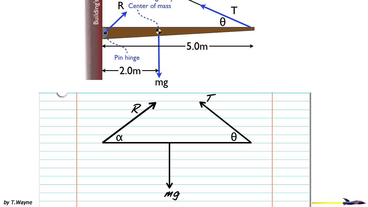
Torque; and objects in equilibrium - Boston University There are three equivalent ways to determine this torque, as shown in the diagram below. Method 1 - In method one, simply measure r from the hinge along the rod to where the force is applied, multiply by the force, and then multiply by the sine of the angle between the rod (the line you measure r along) and the force.

Nov 3 homework
PDF Torque Torque and Rotational Inertia - Boston University Torque and Rotational Inertia 2 Torque Torque is the rotational equivalence of force. So, a net torque will cause an object to rotate with an angular ... Draw a free-body diagram for a horizontal rod that is hinged at one end. The rod is held horizontal by an upward force

Torque and Equilibrium Questions
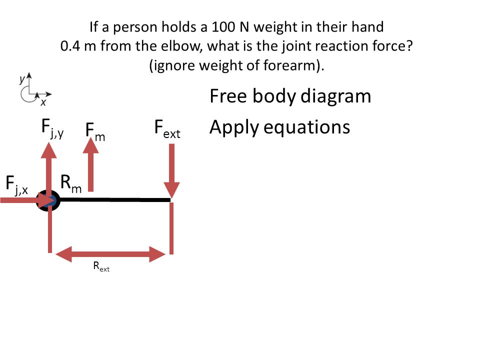
Basic Biomechanics: Moment Arm & Torque Torque = Force (Fm) x Moment Arm Free-Body Force Diagrams allow for identification of all the components of a force system (including torque) Torque in Biomechanics Torque is what creates biomechanical movement. It is what creates the movement of the lever system (bones). This is important to understand.

Torque and Equilibrium Questions
MT&T: LESSON 19. Traction mechanics Fig 2.1 (a) Pull- torque slip relation for wheels on soil, (b) Free body diagram of a towed wheel and, (c) Free body diagram of a driving wheel. The curves presented in Fig. 2.1(a) represent a given soil strength, tire size, and load. As soil strength increases, the curves move upward to the left, as soil strength decreases, they move downward ...

Free Body Diagram of a Wheel | Download Scientific Diagram
Balancing torques in a free body diagram: What point ... newtonian-mechanics torque free-body-diagram. Share. Cite. Improve this question. Follow asked Jun 17, 2015 at 23:26. GGutow GGutow. 3 2 2 bronze badges $\endgroup$ 2. 1 $\begingroup$ About every point in the object the net torque will be zero $\endgroup$ - eepperly16.
Chapter 12 Torque
Equilibrium and Free-body Diagrams and Torques in ... Compute both the force and torque exerted by the weight on the meter stick and record them in Table 1. Record the force exerted on each of the springs in Table 1. Shift the weight to the left by 0.2 m and repeat steps 1.6-1.7. Shift the weight to the left an additional 0.2 m, so the total displacement from the center of the meter stick is 0.4 m.
How to Draw Free-Body Diagrams in Physics
1.5-3: Free body Diagrams with torque - YouTube Basic static equilibrium examples that emphasize drawing the free body diagram, choosing an axis, and evaluating torque without bothering to work out the num...

Extended Free Body Diagrams
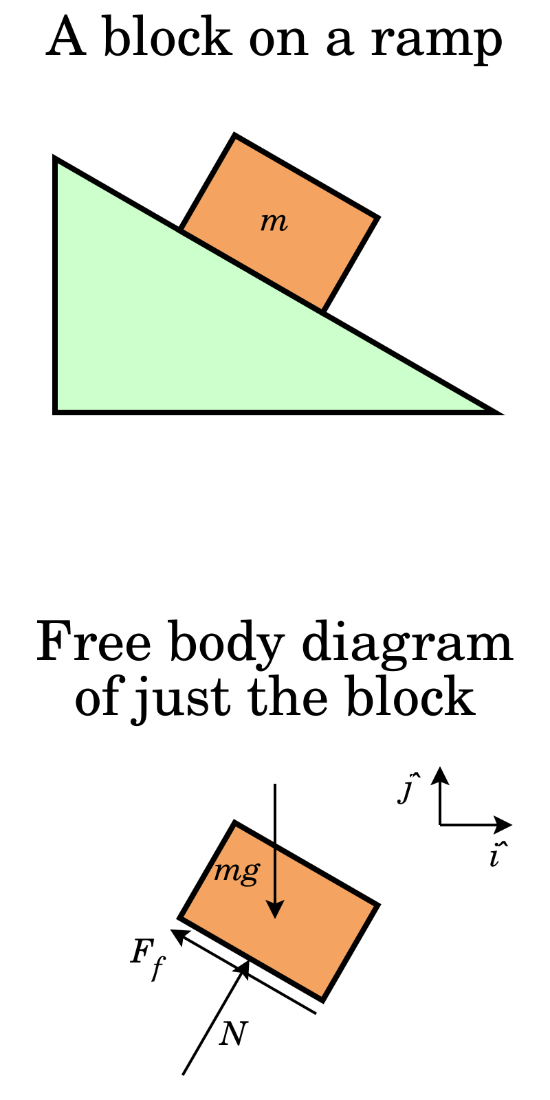
FREE BODY DIAGRAMS. Introduction: A free body diagram is a picture of the forces which act on an object and is the first (and perhaps the most important) step in solving force problems. Purpose: The purpose of the free body diagram (FBD) is to help you identify and analyze the forces that act on a particular object or body.

Torque Free Body Diagrams - Torque Project
Calculating the torque angle in a free-body diagram ... I am primarily talking about this particular force diagram in the attachment of the OP. Nov 25, 2015 #6 sophiecentaur Science Advisor Gold Member 27,129 5,868 OK, so you have the force and you can easily calculate the perpendicular distance. Just drop a perpendicular from the pivot to the line of the string and find its length.
What is the Torque (T) due to force F - ppt download
Chapter 12 Torque

Torque and Rotational Motion Tutorial | Physics

A cylinder rolls up an inclined plane and then rolls down ...
Physics 121C Mechanics
Torque/Force Diagrams
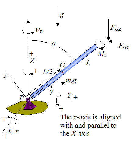
Gyroscope Physics
![183_notes:torquediagram [Projects & Practices in Physics]](https://msuperl.org/wikis/pcubed/lib/exe/fetch.php?w=400&tok=19bb88&media=183_notes:week12_torquediagrams2.png)
183_notes:torquediagram [Projects & Practices in Physics]
Free Body Diagrams Archives - AP Physics C
Extended Free Body Diagram Tutorial
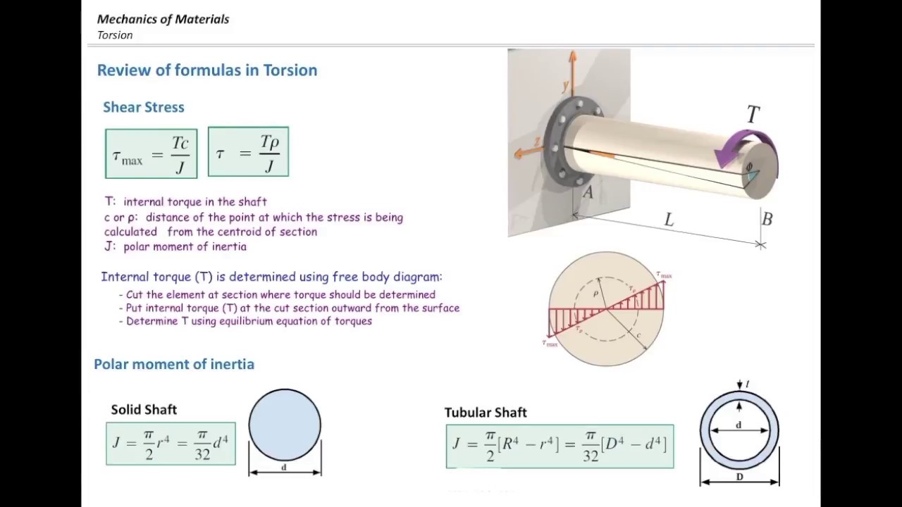
Torsional stress part2, Free body diagram and examples

Free Body Diagram For Torque | Passing the Torque

1.5-3: Free body Diagrams with torque

Joint Torque

Torque and equilibrium review (article) | Khan Academy
Chapter 8 Rotational Equilibrium and Rotational Dynamics Force
Chapter 12 Torque
Proper free-body diagram for a shaft experiencing multiple ...
Ch08

A6_S18 - Physics 5 Labs
Torque; and objects in equilibrium

Free body diagram showing the forces and torques generated by ...
Questions on Torque - Torque Research Project
free body diagram for pulley
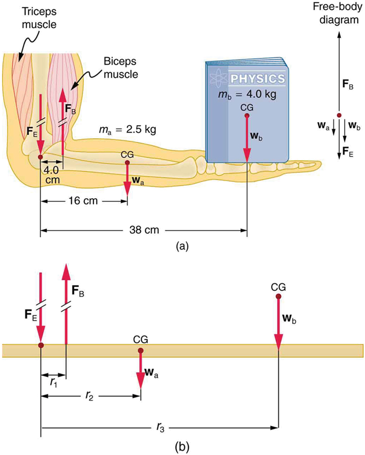
Forces and Torques in Muscles and Joints | Physics
Physics 121C Mechanics
Solved] Body Incomplete FBD 1. Bell crank supporting mass m ...
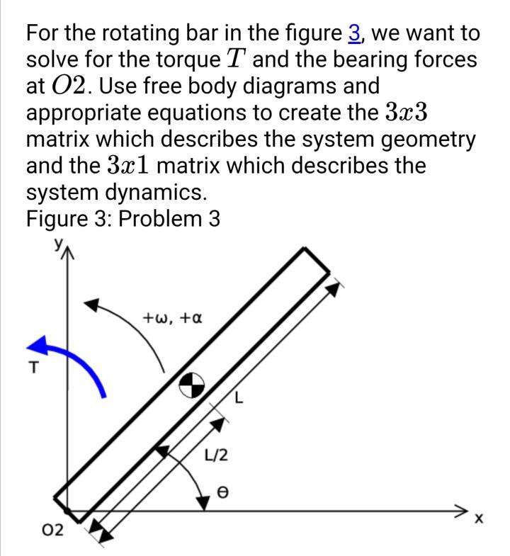
Solved For the rotating bar in the figure 3, we want to ...
0 Response to "41 torque free body diagram"
Post a Comment