37 how to calculate shear force and bending moment with diagram pdf
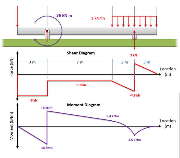
the shear force V and the bending moment M at D from equations of equilibrium, it is found RA = 40 kN RB = 48 kN at section D Fy = 0 40 - 28 - 6 x 5 - V = 0 V = - 18 kN M = 0 - 40 x 5 + 28 x 2 + 6 x 5 x 2.5 + M = 0 M = 69 kN-m from the free body diagram of the right-hand part, same results can be obtained 4.4 Relationships Between Loads, Shear ... Problem 10: Bending Moment and Shear force A beam with a hinge is loaded as above. Draw the shear force and bending moment diagram. Solution: Concept: A hinge can transfer axial force and shear force but not bending moment. So, bending moment at the hinge location is zero. Also, without the hinge, the system is statically indeterminate (to a ...
A = Area of shear force diagram between A and B Concentrated Couples Causes an abrupt change in bending moment Shear and Bending Moment Diagrams: The loading on most beams is such that the stress resultant on planes perpendicular to the axis of the beam consists of a shear force, V, and a bending moment, M. In
How to calculate shear force and bending moment with diagram pdf
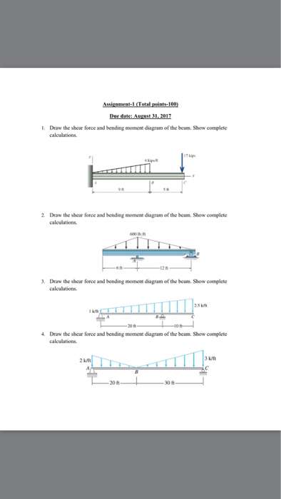
In this article Learn :cantilever beam Bending moment diagram B.M.D. and shear force diagram S.F.D. of a cantilever beam having point load at the end,several point loads,U.D.L. Over Whole Span ,U.D.L. not over the whole span,U.D.L. from support to some distance,U.D.L. Somewhere on the beam,Combination of Point Loads and U.D.L. Write the equation for the shearing force and bending moment diagram at any position in the simply supported beam subjected to uniformly distributed load over.33 pages a) Calculate the shear force and bending moment for the beam subjected to a concentrated load as shown in the figure. Then, draw the shear force diagram (SFD) and bending moment diagram (BMD). b) If P = 20 kN and L = 6 m, draw the SFD and BMD for the beam. P kN L/2 L/2 A B EXAMPLE 4
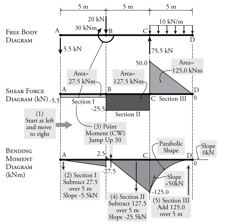
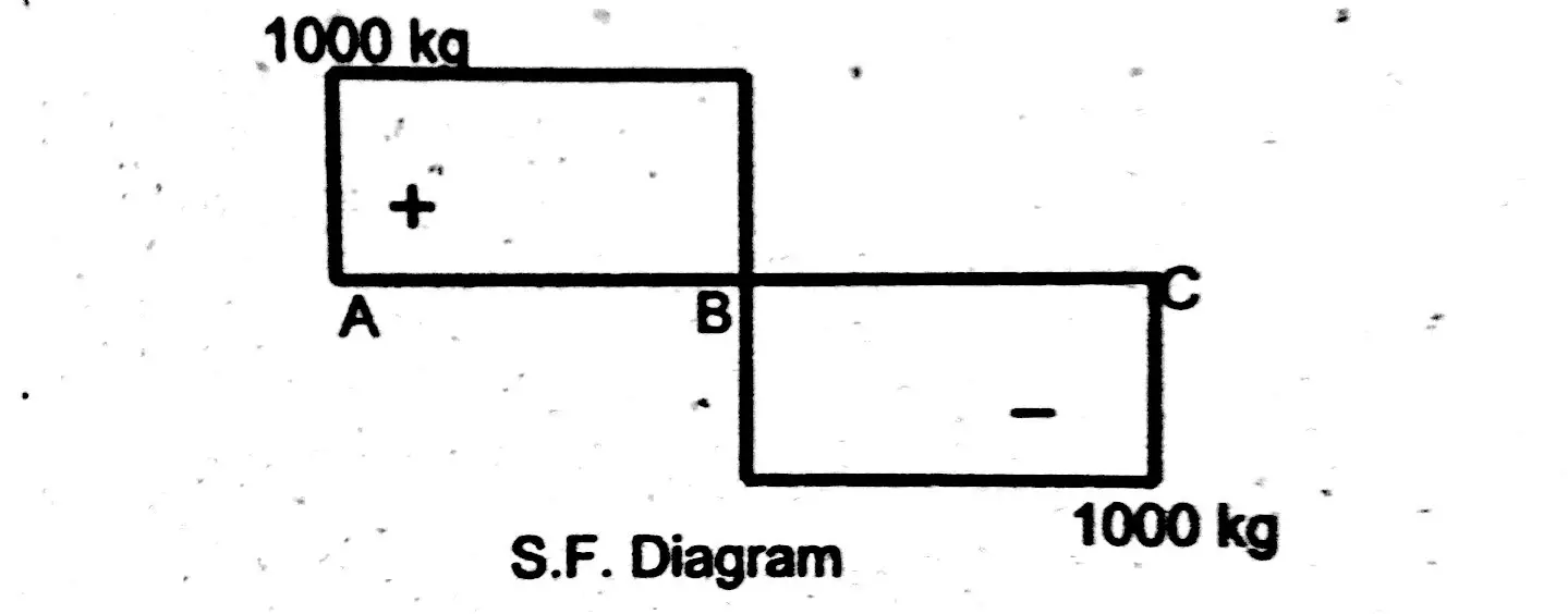
How to calculate shear force and bending moment with diagram pdf. 4.0 Building Shear and Moment Diagrams. In the last section we worked out how to evaluate the internal shear force and bending moment at a discrete location using imaginary cuts. But to draw a shear force and bending moment diagram, we need to know how these values change across the structure. A bending moment diagram is one which shows variation in bending moment along the length of the beam. Example 1 Draw the shear force and bending moment diagrams for the beam shown below a) determine the reactions at the supports. Taking moments about A (clockwise moments =anti-clockwise moments) 10 x2 = 5RC 5RC=20 RC=20/5 =4kN Resolving vertically PDF_C8_b (Shear Forces and Bending Moments in Beams) Q6: A simply supported beam with a triangularly distributed downward load is shown in Fig. Calculate reaction; draw shear force diagram; find location of V=0; calculate maximum moment, and draw the moment diagram. 6k/ft 9 ft RA = (27k)(9-6)/9= 9k A B F = (0.5x6x9) = 27k x = (2/3)(9) = 6 ft Calculating Shear Force Diagram - Step 2: Keep moving across the beam, stopping at every load that acts on the beam. When you get to a load, add to the Shear Force Diagram by the amount of the force. In this case we have come to a negative 20kN force, so we will minus 20kN from the existing 10kN. i.e. 10kN - 20kN = -10kN.
BEAM DIAGRAMS AND FORMULAS Table 3-23 (continued) Shears, Moments and Deflections 13. BEAM FIXED AT ONE END, SUPPORTED AT OTHER-CONCENTRATED LOAD AT CENTER Shear and Moment Diagrams Calculate and draw the shear force and bending moment equations for the given structure. 11 Sketching the Deflected Shape of a Beam or Frame Qualitative Deflected Shape (elastic curve) ≡ a rough (usually exaggerated) sketch of the neutral surface of the structure in the deformed position under the action To find the maximum bending stress •Draw shear & bending moment diagrams •Find maximum moment, M, from bending moment diagram •Calculate cross-section properties -Centroid (neutral axis) -Calculate Area Moment of Inertia about x-axis, I x -Find the farthest distance from neutral axis for cross section, c •Max Bending Normal Stress = x Shear and moment diagrams and formulas are excerpted from the Western Woods Use Book, 4th edition, and are provided herein as a courtesy of Western Wood Products Association. Introduction Notations Relative to “Shear and Moment Diagrams” E = modulus of elasticity, psi I = moment of inertia, in.4 L = span length of the bending member, ft. R = span length of the bending member, in. M ...
CIVL 3121 Shear Force and Bending Moment Diagrams for Frames 1/5. B Cx Shear and Moment Diagrams for Frames Let's start with member AB. 0.8 k/ft. 20 ft. 16 k 11.84 k 16 ft. 0.6 k/ft. 4.16 k 9.6 k 9.6 k 16 ft. MB B y Bx By MB Cy Mc Cy Cx MC Shear and Moment Diagrams for Frames Let's start with member AB. 0.6 k/ft. 4.16 k The shear force and bending moment diagram gives a clear picture in our mind about the variation of SF and BM throughout the entire section of the beam. Further, the determination of value of bending moment as a function of ‘x' becomes very important so as to determine the value of deflection of beam subjected to a given loading where we will use the formula, 2 2 x dy EI M dx. 4.2 Notation ... = 6internal bending moment = name for a moment vector n = number of connectors across a joint n.a. = shorthand for neutral axis (N.A.) O = name for reference origin p = pitch of connector spacing P = name for a force vector q = shear per length (shear flow) Q = first moment area about a neutral axis Q connected = first moment area about a neutral Axial Force, Shear Force and Bending Moment Diagrams for Plane Frames Previous definitions developed for shear forces and bending moments are valid for both beam and frame structures. However, application of these definitions, developed for a horizontal beam, to a frame structure will require some adjustments.
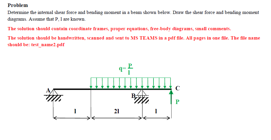
Solved Problem Determine The Internal Shear Force And Chegg Com
Using superposition, calculate the force that ... Find the reactions and draw the Shear Force and Bending Moment Diagrams of the beam. ForceMethod Page 5 . Example: Frames ... • Draw the influence lines for the shear -force and bending -moment at point C for the following beam.
2
Normal Force (τ ) (σ) Shear Forces z x y V P y V x Torsional Moment (τ ) (σ) Bending Moments z x y M T y M x or Torque Force Components Moment Components "Cut Surface" "Cut Surface" Centroid of Cross Section Centroid of Cross Section Normal Force: Axial Force z x y P Centroid σ Axial Stress "Cut Surface" σ = P A l Uniform over the entire ...

Stress Engineering Interview Questions Part 1
About the Beam Calculator. Welcome to our free online bending moment and shear force diagram calculator which can generate the Reactions, Shear Force Diagrams (SFD) and Bending Moment Diagrams (BMD) of a cantilever beam or simply supported beam. Use this beam span calculator to determine the reactions at the supports, draw the shear and moment ...

Shear Force Diagram An Overview Sciencedirect Topics
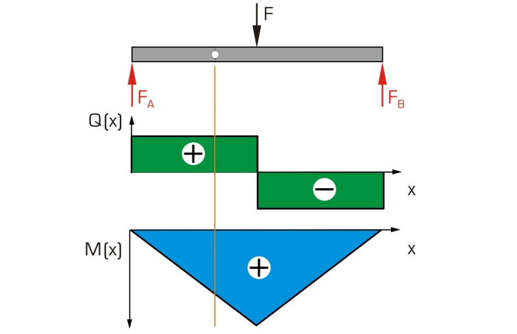
Fig. 18 Shear force and bending moment diagram . Fig. 19 Loading in beams, shear force and bending moment At every section in a beam carrying transverse loads there will be resultant forces on either side of the section which, for equilibrium, must be equal and opposite, and whose combined action tends to shear the section in one of the two ways. The shearing force (S.F.) at the section is ...

Learn How To Draw Shear Force And Bending Moment Diagrams Engineering Di Mechanical Engineering Design Mechanical Engineering Civil Engineering Construction
0 + (area under the shear diagram from x 0 to x) If there is no externally applied moment M 0 at x 0 = 0, total moment at any section equals the area under the shear diagram up to that section When V passes through zero and is a continuous function of x with dV/dx ≠ 0(i.e., nonzero loading) BM will be a maximum or minimum at this point

Bending Moment Wikipedia
a) Calculate the shear force and bending moment for the beam subjected to a concentrated load as shown in the figure. Then, draw the shear force diagram ...77 pages

Shear Force And Bending Moment Diagram Practice Problem 1 Youtube
Being able to draw shear force diagrams (SFD) and bending moment diagrams (BMD) is a critical skill for any student studying statics, mechanics of materials, or structural engineering. There is a long way and a quick way to do them. The long way is more comprehensive, and generates expressions for internal shear and internal bending moment in ...
1
The shear force and bending moment diagrams are convenient visual references to the internal forces in a beam; in particular, they identify the maximum values of V and M. a. Sign conventions ( )k/lblihi/h i Figure 4.3 Sign conventions for external loads; shear force, and bending moment. b. Procedure for determining shear force and bending moment diagrams ٠Compute the support reactions from ...
Analysis Of Beams Shear Force Bending Moment Diagram
need this information to calculate the maximum shear stress and the maximum bending stress in a beam. The moment diagram can also be used to predict the qualitative shape of the deflected axis of a beam. General Guidelines on Construction of SFD and BMD Before we go on to solving problems, several standard procedures (or practices) in relation with construction of shear force and bending ...
2
Shear Force and Bending Moment Diagram for simply supported beam version 1.0.0.0 (3.44 KB) by Sajeer Modavan This Matlab code can be used for finding Support reaction, Maximum Bending Moment, SFD and BMD

The Ultimate Guide To Shear And Moment Diagrams Degreetutors Com
3.2 - Shear Force & Bending Moment Diagrams What if we sectioned the beam and exposed internal forces and moments. This exposes the internal Normal Force Shear Force Bending Moment ! What if we performed many section at ifferent values Of x, we will be able to plot the internal forces and bending moments, N(x), V(x), M(x) as a function Of position!

Stress Engineering Interview Questions Part 1
Problem 4.3-1 Calculate the shear force V and bending moment M ... Draw the shear-force and bending-moment diagrams for this beam.26 pages

Shear Force And Bending Moment Diagrams Graphical Method Slide Share
moments are developed and the terms shear force and bending moments come into ... From Equation (1), the area of the shear force diagram between any two ...13 pages

6 Le Moment D Une Force
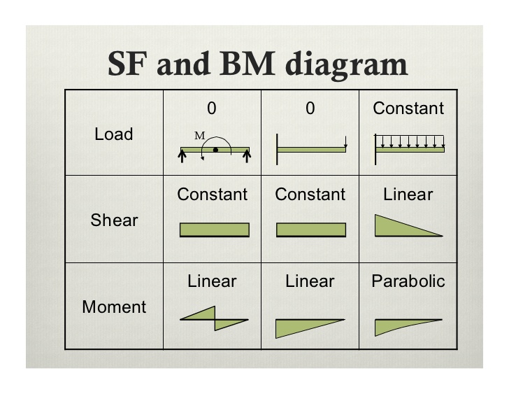
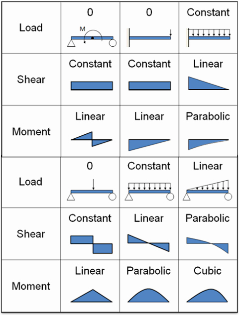
Step 2: Step 1: Knowing Forces Effect on Beams. - Knowing how different forces effect beams is important to be able to calculate the shear and bending moments. - A point force will cause a rectangular shear and a triangular bending moment. - A rectangular distributed load will cause a triangular shear and a quadratic bending moment.

Engr10005 Tutorial Week 7 Bending Moment And Shear Force 1 Pdf Engr10005 Statics T07 Tutorial 7 Shear Force And Bending Moment Questions Part A Course Hero
Statics of Bending: Shear and Bending Moment Diagrams David Roylance Department of Materials Science and Engineering Massachusetts Institute of Technology

Shear In Bending
a) Calculate the shear force and bending moment for the beam subjected to a concentrated load as shown in the figure. Then, draw the shear force diagram (SFD) and bending moment diagram (BMD). b) If P = 20 kN and L = 6 m, draw the SFD and BMD for the beam. P kN L/2 L/2 A B EXAMPLE 4
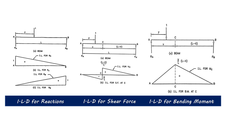
Influence Line Diagrams For Structural Analysis Technical Civil
Write the equation for the shearing force and bending moment diagram at any position in the simply supported beam subjected to uniformly distributed load over.33 pages
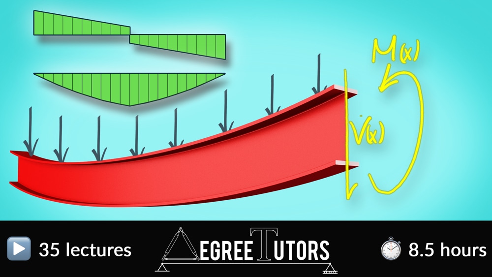
The Ultimate Guide To Shear And Moment Diagrams Degreetutors Com
In this article Learn :cantilever beam Bending moment diagram B.M.D. and shear force diagram S.F.D. of a cantilever beam having point load at the end,several point loads,U.D.L. Over Whole Span ,U.D.L. not over the whole span,U.D.L. from support to some distance,U.D.L. Somewhere on the beam,Combination of Point Loads and U.D.L.
Shear Force And Bending Moment Diagrams Notes For Mechanical Engineering Ese Gate Me Gradeup Byju S Exam Prep
Bending Moment And Shear Force Calculation Quick And Easy
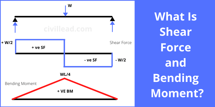
What Is Shear Force And Bending Moment Civil Lead
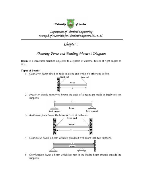
Chapter 3 Shearing Force And Bending Moment Diagram Fet
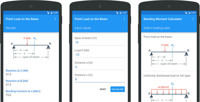
Bending Moment Calculator A Free Application To Calculate The Bending Moment And Shear Force Constructupdate Com
2

Gate Ese Shear Force Diagram Of Beam Subjected To Varying Load Offered By Unacademy

Mechanics Of Materials Pages 151 200 Flip Pdf Download Fliphtml5

Shear Force And Bending Moment Diagrams Wikiversity
Mechanics Map Shear And Moment Diagrams
Solved The Shear Force Diagram Of A Loaded Beam Is Shown In The Fol

Pdf Chapter 5 Bending Moments And Shear Force Diagrams For Beams 5 0 Shear Force And Bending Moments Diagrams For Beams Petrus Guntur Supradana Academia Edu
Shear Force And Bending Moment Diagrams Graphical Method Slide Share
How To Draw Shear Force Bending Moment Diagram Simply Supported Beam Examples Engineering Intro
Solved Draw The Shear Force And Bending Moment Diagram Of The Beam Show 1 Answer Transtutors
Products
1
1

How To Calculate And Draw Shear And Bending Moment Diagrams 13 Steps Instructables
0 Response to "37 how to calculate shear force and bending moment with diagram pdf"
Post a Comment