38 hot gas bypass diagram
a 3-way solenoid valve to bypass hot refrigerant gas to a reheat coil that is placed after the cooling coil. The 3-way valve is usually controlled by a humidistat in the space that allows the unit to continue the moisture removal process after the dry bulb thermostat has been satisfied. ... hot gas passing through the evaporator (blow-by gas) represents 24% of the injected hot gas for Pressure Control system, whereas for the Liquid Drain method it only represents 3%. If the defrost process is not terminated after 17 minutes, the losses will increase further. For the Pressure Control system,
The Hot Gas Bypass Valve Explained By Gary McCreadie. Hot gas bypass valves are a simple and very effective way to add a false load on an evaporator coil. What is a false load you ask. Well, as we have learned in the past, refrigerant pressures are directly related to the ambient temperature surrounding them.

Hot gas bypass diagram
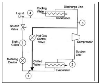
July 9, 2007. Hot gas bypass is recommended when the load on an evaporator varies and operation of the air conditioning system is desired at lower than design conditions. Additionally, hot gas bypass is used when the evaporator coil is designed for comfort cooling (latent and sensible loads) versus precision cooling (all sensible loading). Hot Gas Bypass (HGBP) and the Pressure Enthalpy Diagram. Hot gas bypass (also called discharge bypass) is a feature in a refrigeration system uses to satisfy the mechanical needs of the system during low load conditions. Low load conditions can lead to frosting or freezing the evaporator, refrigerant flood back to the compressor, system ... Hot gas bypass application diagram keys . ① Temperature Controller . ② Check Valve: It is important to install a check valve just after T-connection as shown. Check valve will not allow return of liquid refrigerant from condenser through electrical control
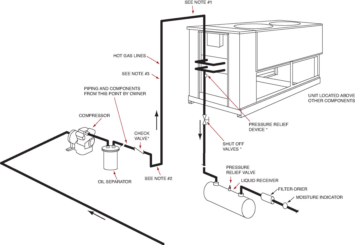
Hot gas bypass diagram. The discharge bypass valve should always be installed at the condensing unit rather than at the evaporator section. Not only will this ensure the rated bypass capacity of the valve but it will eliminate the possibility of hot gas con-densing in the bypass line (especially on remote systems). With the hot gas bypass option now no longer needed, additional energy savings can be attained with the ability to modulate compressor operation down to 10% of total capacity. The power input to the condenser fan(s) is also reduced as head pressure is tracked. 4. See all my HVAC Webinars at 👉 https://insightpartners.lpages.co/ 👈In this video, we compare Hot Gas Bypass to the Emerson Digital Compressor. HOT GAS BYPAS... FIG. 3 is an electrical schematic diagram of the control circuit which forms a part of the hot gas bypass defrosting system of FIG. 1; and . FIG. 4 is a partial block diagram of a second embodiment of a hot gas bypass defrosting system according to the present invention. DESCRIPTION OF THE PREFERRED EMBODIMENT
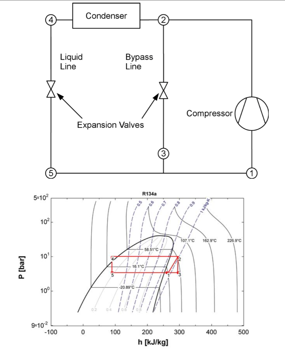
• Hot gas bypass to the evaporator inlet • Modulating hot gas reheat • Suction service valves • Replaceable core filter driers • High capacity options via compressor and/or coils • High efficiency options via supply fan and/or coils • Corrosion protected condenser and/or evaporator coil Cabinet • Extended casing (SX models) The hot gas bypass valve monitors the outlet pressure of the evaporator and will begin to modulate open as the load on the unit decreases to the point where the evaporator temperature is at the setpoint of the bypass valve. The bypass valves are factory adjusted to a setting of 61 psig (35°F evaporator temperature). This We provide the following diagram to illustrate how a HGBP mechanism works. The following diagram, although simple, shows the intuition behind a HGBP method for cycle control of a refrigeration system. There are different methods to piping a hot gas bypass system however the one displayed here is most typical in the industry. The hot gas bypass line on the circuit runs from the discharge line of the compressor to the liquid line connection at the evaporator. Figure 4: Indoor Chiller with Remote Air-cooled Condenser Air Cooled Condenser Discharge line inverted trap (can be replaced with a check valve) Discharge Line Liquid Line Riser
The hot gas bypass valve is a mechanical valve used to introduce a false load into the evaporator and used on systems with varying loads, process chillers fo... Figure 16 - Reheat/Hot Gas Bypass Piping Diagram with air handler above condenser ..... 50 Figure 17 - Reheat/Hot Gas Bypass Piping Diagram with air handler below condenser ..... 51 Figure 18 - Reheat/Hot Gas Bypass Piping Diagram with air handler evaporator above condenser and field Fig - 1: Schematic diagram of HGBD cycle Fig-1 shows the schematic diagram of hot gas bypass defrosting method. Setup include basic components of refrigeration cycle- compressor, indoor and outdoor coil, expansion valve and accumulator. In this figure we can see that discharge of hot gas stream is bypassed from the hot gas defrost process. First, when the hot gas valve is sud-denly opened and any condensate in the hot gas line or residual cold liquid in the coil is propelled by the high-pressure vapor. Second, is at the conclusion of defrost, when liquid conden-sate inside the coil is suddenly released to the low side of the system.
Schematic diagram of a hot gas bypass test bench for the ...
RE: Centrifugal Compressor Hot Gas Bypass. georgeverghese (Chemical) 20 Mar 15 05:02. Hot gas bypass feature on centrifugals are some times necessary to keep the compressor away from surge on sudden shutdown. Though I'm not party to this particular design, the valve capacity on a HGB ( which is usually a quick open high capacity ball valve) may ...

Schematic of a typical adsorption cooling system ...
Hot gas bypass is recommended when the load on an evaporator varies and operation of the air conditioning system is desired at lower than design conditions. Additionally, hot gas bypass is used when the evaporator coil is designed for comfort cooling (latent and sensible loads) versus
Rooftop Modifications - Products | Thybar
shows the PH diagram of R-22, indicating liquid, saturated mixture, and gaseous states. The top of the saturated "dome" is the critical point. Above this point, the refrigerant is not considered liquid or gas, but an undefined fluid.

8.4 Freeze protection - SWEP
The purpose of a hot gas bypass system is to artificially load the compressor upon a decrease in evaporator load. TheHotGasBypass(HGBP)regulatorvalveautomatically responds to changes in suction pressure.When the refrigerant evaporating pressure is above the bypass valve setting, the valve remains closed.When the cooling
cs tid 20 - 250 p & i diagram 4 3.4 schematic diagrams cs tid 300 - 500 p & i diagram instruction manual - coldspell reference : manual version 2 refrigerant line air line electrical line in air adv out air integrated heat exchanger demister pre balance line freon dryer hot gas bypass valve expansion device hp/lp ref. compressor air/air heat ...
Centrifugal Chiller - Fundamentals | Energy-Models.com
O Hot Gas bypass piping (optional) *† *Supplied on RFS units †Supplied on RCS units. McQuay IM 893-1 7 Introduction ... the wiring diagram legend, which is included in "Wiring Diagrams" on page 55. Figure 7: Control Locations—RPS units R eturn air economizer Filter se ction Supply fan Heat DX

Legend of the Seven Lights, Chapter 66
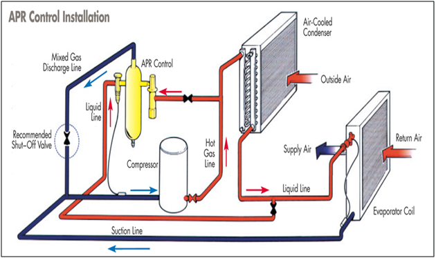
8) External equalizers on sides of APR Control hot gas valve should be connected to the suction line between mixed gas discharge connection from the APR Control and compressor inlet. 9) The injection valve bulb and Hot Gas Bypass valve bulb must be mounted, and insulated, to the suction line between compressor and mixed gas discharge connection ...
Refrigeration: Refrigeration Piping Diagrams
The hot gas bypass valve monitors the outlet pressure of the evaporator and will begin to modulate open as the load on the unit decreases to the point where the evaporator temperature is at the setpoint of the bypass valve. The bypass valves are factory adjusted to a setting of 68 psig (40°F evaporator temperature). This

hot gas defrost - YouTube
remote system, bypass to the evaporator inlet is still the best method of hot gas bypass to insure good oil return to the com-pressor. When this is done, the bypass valve must be located at the compressor rather than at the evaporator section. This will insure obtaining rated capacity from the bypass valve at the conditions for which it was ...

On Explosions and Scoops 2NI
Over the years I have noticed that there is some confusion as to what each are, what they do and when you need them. This article is written to clear things up. To start, the vapor/compression cycle of typical air conditioning is this: Heat transfers from the space to the evaporator coil and refrigerant in the

Refrigeration: Hot Gas Bypass Refrigeration System
Hot Gas Bypass It's not enough to deliver an HVAC system that meets the unique needs of each application. The owner also deserves a system that is the most reliable and the least costly to operate. In specific cases, adding hot gas bypass to the refrigeration system may be necessary in order to achieve all three goals. But more often than not,

Schematic diagram of a hot gas bypass test bench for the ...
Hot gas bypass application diagram keys . ① Temperature Controller . ② Check Valve: It is important to install a check valve just after T-connection as shown. Check valve will not allow return of liquid refrigerant from condenser through electrical control
Hot Gas Bypass (HGBP) and the Pressure Enthalpy Diagram. Hot gas bypass (also called discharge bypass) is a feature in a refrigeration system uses to satisfy the mechanical needs of the system during low load conditions. Low load conditions can lead to frosting or freezing the evaporator, refrigerant flood back to the compressor, system ...

Refrigeration: Refrigeration Hot Gas Piping
July 9, 2007. Hot gas bypass is recommended when the load on an evaporator varies and operation of the air conditioning system is desired at lower than design conditions. Additionally, hot gas bypass is used when the evaporator coil is designed for comfort cooling (latent and sensible loads) versus precision cooling (all sensible loading).

Aliexpress.com : Buy 15.84KW R404a hot gas bypass valve ...

Hot Gas Bypass - Revisited | York Central Tech Talk

Schematic diagram of hot-gas bypass compressor load stand ...

Rv Hot Water Heater Bypass Valve Diagram - Ekerekizul

Patent US6286322 - Hot gas defrost refrigeration system ...

Discharge Gas Bypass Valve - Manik Engineers

Refrigeration: Bypass Line Refrigeration

Understanding Hot Gas Bypass

Schematic diagram of a hot gas bypass test bench for the ...

Refrigeration: Refrigeration Hot Gas Defrost

Schematic diagram of a hot gas bypass test bench for the ...

Schematic diagram of a hot gas bypass test bench for the ...

Frog, Deep Sea World, North Queensferry, Fife, Scotland.
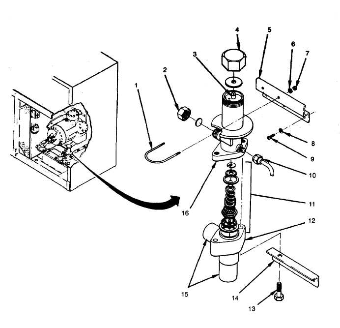
Figure 5-26. Hot Gas Bypass Valve
To Measure The Performance Of A Compressor, A Hot ...

Refrigeration: Refrigeration Hot Gas Bypass Valve

Schematic diagram of a hot gas bypass test bench for the ...

Helicopter, Niagara Falls State Park, New York State, United States Of America.
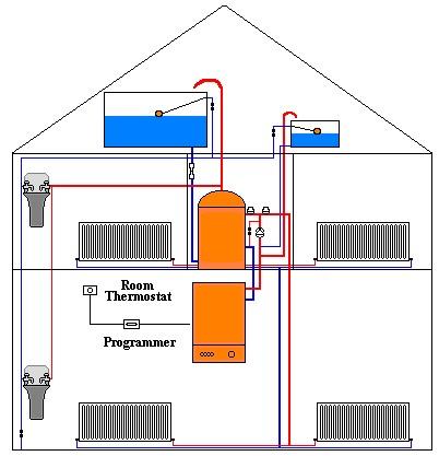
Conventional Central Heating Mystery Pipe? | Page 3 ...

discharge bypass valve connection

Steam Boiler: Steam Boiler Piping Diagram
Stonewood Endurance Guide and Reference Map

P-h diagram in a hot-gas bypass test stand. | Download ...
0 Response to "38 hot gas bypass diagram"
Post a Comment