40 how to draw axial force diagram
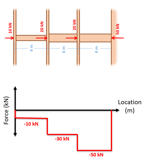
Determine axial/shear forces. Draw axial/shear force diagrams. Determine bending moment. Draw bending moment diagram. Example 1. This is a beam with distributed and point loads. Before we begin, we should think about the following: What are the bending moments at the supports? What are the shapes of the AFD, SFD, and BMD? View Solution. Example 2. This is a similar beam to the one in Example 1 ... Lined up below the free body diagram, draw a set of axes. The x-axis will represent the location (lined up with the free body diagram above), and the y-axis will represent the internal shear force. Starting at zero at the right side of the plot, you will move to the right, pay attention to forces in the free body diagram above.
A force is applied to two blocks in contact, as shown. Strategy. Draw a free-body diagram for each block. Be sure to consider Newton's third law at the interface where the two blocks touch. Solution. Significance[latex]{\mathbf{\overset{\to }{A}}}_{21}[/latex] is the action force of block 2 on block 1.
How to draw axial force diagram
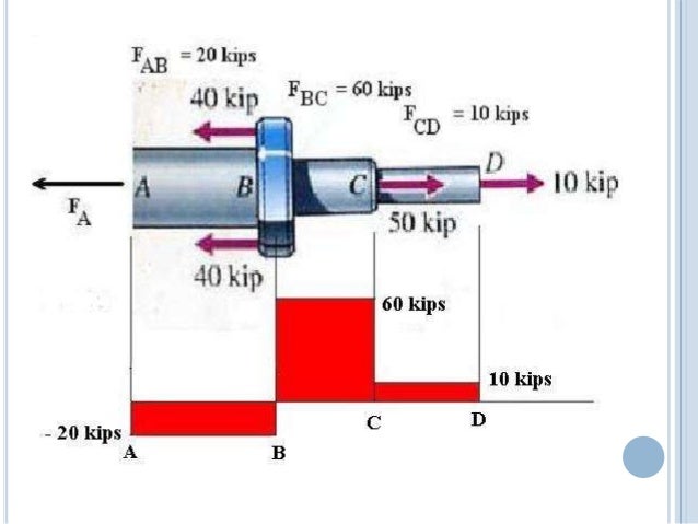
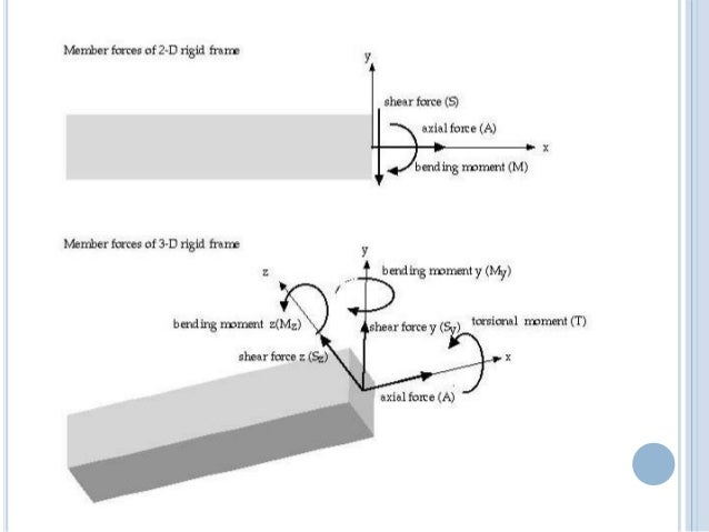
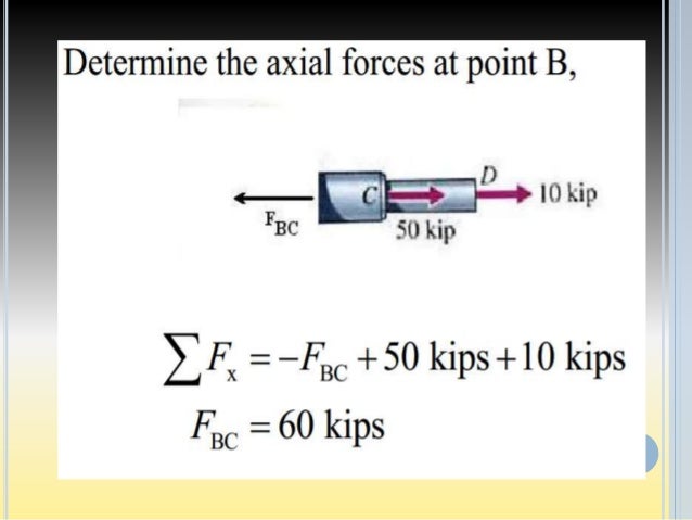
Axial Force, Shear Force and Bending Moment Diagrams for Plane Frames Previous definitions developed for shear forces and bending moments are valid for both beam and frame structures. However, application of these definitions, developed for a horizontal beam, to a frame structure will require some adjustments. Determine the axial forces transmitted by transverse cross sections in intervals AB, BC, and CD of the bar. Draw an axial force diagram for the bar. 6. Drawn the axial force diagram.All of the forces are in tension. 7. AFD OF THE BEAMS LOADED AXIALLY BY THE CONCENTRATED LOADS Simply Supported Beam 8. CANTILEVER BEAM 9. About Press Copyright Contact us Creators Advertise Developers Terms Privacy Policy & Safety How YouTube works Test new features Press Copyright Contact us Creators ...
How to draw axial force diagram. Perpendicular loads on a beam affect only the shear force and bending moment within the beam, not the axial force In this case, axial force is zero anywhere along the beam. The functions and and their diagrams (graphs or plots) provide powerful tools for evaluating the values and variations of the shear force and bending moment at any point. Setting the bending diagrams of beam. Calculate the reactions at the supports of a beam. Bending moment diagram (BMD) Shear force diagram (SFD) Axial force diagram. Invert Diagram of Moment (BMD) - Moment is positive, when tension at the bottom of the beam. Consider a straight two-force member AB subjected at A and B to equal and opposite forces F and -F directed along AB. Cutting the member AB at C A B C F-F F C -F A and drawing the free-body diagram of portion AC, we conclude that the internal forces which existed at C in member AB are equivalent to an axial force-F equal and opposite to F. For a two-force member which is Answer (1 of 2): It really is simple once you understand it. Axial forces are the most simple of them all. Assuming you have solved for reaction forces, first of all choose a consistent direction to go through your beams. Let’s say we start at A and finish at E. For every beam segment, look at t...
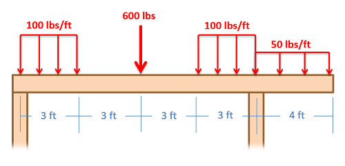
Draw axial force, shear force and bending moment diagrams for the beam shown below. Demonstrate sing convention and all the calculations. What is Cross section, What is Axial Force and Shear Force. What is Axial Load /Axial Force Diagram/ Axial Thrust Diagram, How to Draw Axial Load /Axial Forc... Answer (1 of 2): It really is simple once you understand it. Axial forces are the most simple of them all. Assuming you have solved for reaction forces, first of all choose a consistent direction to go through your beams. Let's say we start at A and finish at E. For every beam segment, look at t... Use the Cantilever Method to draw the axial force, shear force and bending moment diagrams of the three - storied frame structure loaded as shown below. 6 EI 15.9-E A k 15 P 5 15 , P 18k 12k k 12 0 0 42.4 42.4 35.3 13.2-15.9 Beam BMD (k-ft) 64.6 -53.8 The dotted line is the column centerline (at all floors)
We will get to the most important part, which is analyzing frames and beams to calculate their internal forces and to draw axial, shear and moment diagrams. Contrary to most textbook presentations, we will adopt a notation that is universally adopted by engineers when using moment diagrams. 6-11 Rules of Axial Force Diagram 10:11. This video briefly demonstrates the actions of internal loading of a structure followed by indicating bending moment diagrams (BMD), shear force diagrams (SFD) & axial force diagrams (AFD). When any structure is exposed to a loading, the loads are transferred from the point of action through the structural elements down to the base and/or supports. Axial Force Diagrams and Torque Diagrams. As an alternative to splitting a body in half and performing an equilibrium analysis to find the internal forces and moments, we can also use graphical approaches to plot out these internal forces and moments over the length of the body. Where equilibrium analysis is the most straightforward approach to finding the internal forces and moments at one ... (As required) Use the results from each member to draw overall axial force, shear force and bending moment diagrams for the entire frame structure. Example. The analysis of determinate frames will be demonstrated using the example structure shown in Figure 4.8. Draw axial, shear and moment diagrams for all members of the structure.
Axial Force Diagram 10 01 03 025
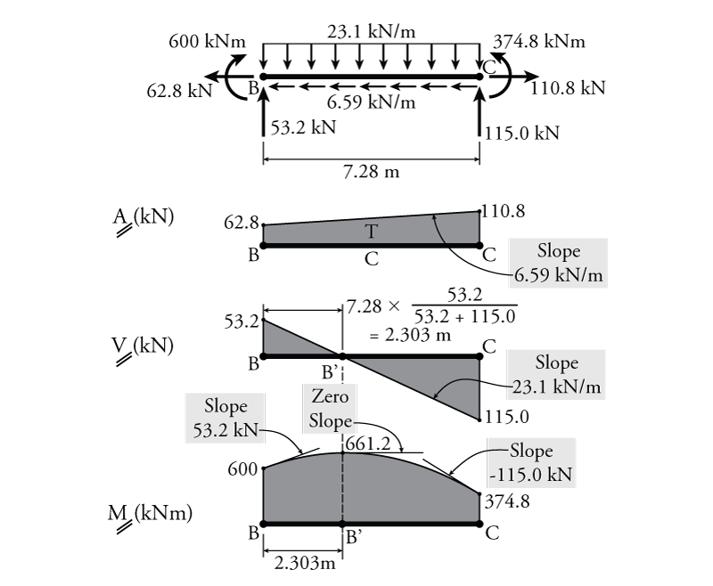
desirable to draw the V-diagram below the FBD of the entire beam, and then draw the M-diagrambelow the V-diagram. The bending moment and shear force diagrams of the beam are composites of the V and M diagrams of the segments. These diagrams are usually discontinuous, or have discontinuous slopes.
Solved Draw The Free Body Fbd Axial Force Afd Shear Chegg Com
Civil Engineering questions and answers. 01) Draw BMD,SD,AFD (axial force diagram) for the following questions. 15. 15 11 25 K B 10 ft 12k 10 11 CA 02) 10 ft "T -10 ft 30k 1.5 ft 16 ft 24 3. Question: 01) Draw BMD,SD,AFD (axial force diagram) for the following questions. 15.

2 2 Axial Force Diagram Sections Ex 2 2 Part I Youtube
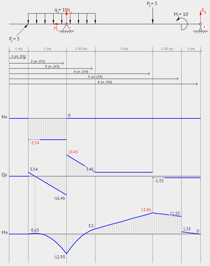
Axial Force, Shear Force and Bending Moment Diagram Draw the Axial Force Diagram (AFD), Shear Force Diagram (SFD) and Bending Moment Diagram (BMD) of the beam loaded as shown below. x 5 The support reactions can be calculated by considering the equilibrium equations of the overall structure;
Determining The Shear Force And Bending Moment Equations Of Simply Supported Beam
Solution for 1. Draw the axial force diagram 2. Write down the governing equations 3. State the boundary conditions 4. Solve the equations for the axial…

Draw An Axial Load Diagram Youtube
WHY AXIAL FORCE DIAGRAM IS IMPORTANT? The challenge with a member is that the internal forces can vary a greatly along the length. So, the diagram is drawn. • The diagram shows the internal forces along the length of the structure. This helps to visualize where the maximum stresses will occur due to axial force or axial loading.
4 4 Determinate Frame Analysis Learn About Structures
4.0 Building Shear and Moment Diagrams. In the last section we worked out how to evaluate the internal shear force and bending moment at a discrete location using imaginary cuts. But to draw a shear force and bending moment diagram, we need to know how these values change across the structure.
Solved P Lm2 Draw The Axial Force Shear Force And Moment Diagrams P V Amp M Of The Following Complex Frame Dimensions Are In M 1 Dkam Illll Course Hero
example of axial force diagram is shown below. <Axial force diagram > Displaying axial force value As the axial force in a truss member is uniform, it is simpler to express the value of the force magnitude by the text than to display its diagram. To display the axial force by text, choose "Axial Force Value" item from menu. If the axial
Axial Force Diagram 10 01 03 025
Nature of diagram: • At the point of action of force, the diagram changes abruptly. • The force acts always along the length of the structure. • The sign convention is very simple, if one direction is taken as positive, then the other is negative. • The nature of forces is compressive or tensile only. Example problem to draw axial force ...
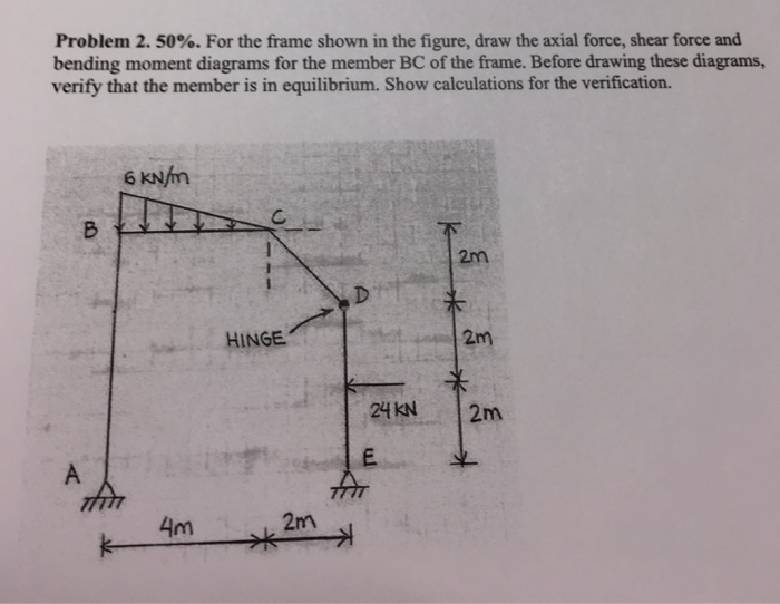
Solved For The Frame Shown In The Figure Draw The Axial Force Shear 1 Answer Transtutors
Internal Force Diagrams. We will get to the most important part, which is analyzing frames and beams to calculate their internal forces and to draw axial, shear and moment diagrams. Contrary to most textbook presentations, we will adopt a notation that is universally adopted by engineers when using moment diagrams.
4 4 Determinate Frame Analysis Learn About Structures
4.5 Practice Problems. For each beam shown below, determine the equations for the axial force, shear force and bending moment as a function of the position along the length of the beam. Use these equations to draw the axial force diagram, shear force diagram, and bending moment diagram.

Draw The Shear Bendin Moment And Axial Force Diagrams And The Qualitative Deflected Shape For The Frame Shown Wegglab
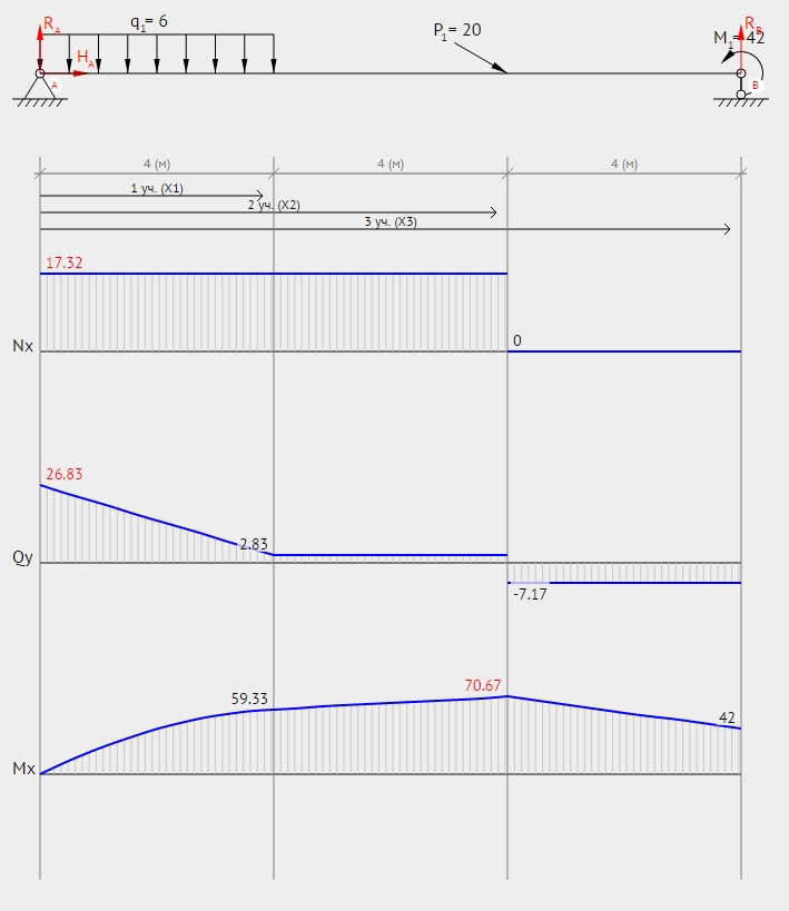
BEAMGURU.COM is a online calculator that generates Bending Moment Diagrams (BMD) and Shear Force Diagrams (SFD), Axial Force Diagrams (AFD) for any statically determinate (most simply supported and cantilever beams) and statically indeterminate beams, frames and trusses.The calculator is fully customisable to suit most beams, frames and trusses; which is a feature unavailable on most other ...
48 Kn 6m 2m 3m 25 Kn M 2 M E 90 Kn Do 717 3 M 7 Course Hero
Continuation of previous video https://www.youtube.com/watch?v=tLXj_T3RL-c&t=32sin this part a tutorial "How to calculate the axial force on this frame struc...

Draw The Shear Bendin Moment And Axial Force Diagrams And The Qualitative Deflected Shape For The Frame Shown Wegglab
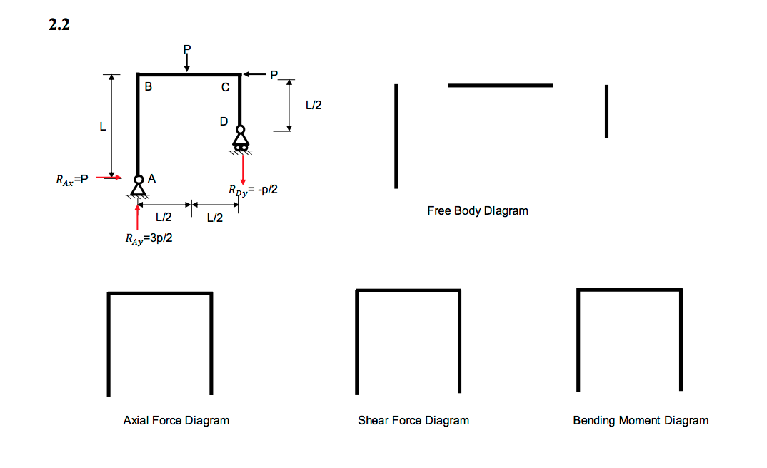
Calculate and draw the axial force, shear force and bending moment equations for the given frame structure. 30 Two-Dimensional Force Transformations x y r Px Py Pn Pt FT (b) FT (a) FT = Force Transformation 31 Suppose you are given the forces in FT (a) and you wish to transform these forces into Pn (normal) and Pt (tangential) as shown in FT (b ...
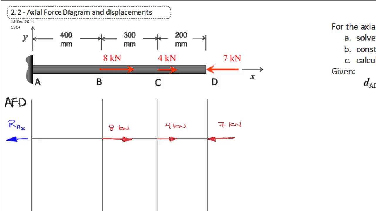
2 2 Axial Force Diagram Reactions Ex 2 2 Part 0 Youtube
http://goo.gl/CQM5ek for more FREE video tutorials covering Mechanics of Solids and Structural MechanicsThis video shows a workout on a comprehensive example...
Mechanics Map Axial Force Diagrams And Torque Diagrams
About Press Copyright Contact us Creators Advertise Developers Terms Privacy Policy & Safety How YouTube works Test new features Press Copyright Contact us Creators ...

How To Draw Axial Force Diagram Axial Load Diagram Axial Thrust Diagram Axial Force Shear Force Youtube
Determine the axial forces transmitted by transverse cross sections in intervals AB, BC, and CD of the bar. Draw an axial force diagram for the bar. 6. Drawn the axial force diagram.All of the forces are in tension. 7. AFD OF THE BEAMS LOADED AXIALLY BY THE CONCENTRATED LOADS Simply Supported Beam 8. CANTILEVER BEAM 9.

Moment Shear And Axial Force Diagrams A Complete Beam B Link And Download Scientific Diagram
Axial Force, Shear Force and Bending Moment Diagrams for Plane Frames Previous definitions developed for shear forces and bending moments are valid for both beam and frame structures. However, application of these definitions, developed for a horizontal beam, to a frame structure will require some adjustments.

Draw Axial Force Shear Force And Bending Moment Diagrams For The Beam Shown Below Demonstrate Sing Convention And All The Calculations Study Com

Method Of Calculating The Axial Force And The Specimen Axial Download Scientific Diagram
Determining The Shear Force And Bending Moment Equations Of Simply Supported Beam

Axial Force Diagrams Obtained From The Structural Analyses Results For Download Scientific Diagram

Understanding Sign Conventions In Structural Analysis Structville

Licensed Electrical Mechanical Engineer Ppt Download
Solved Draw The Shear Bending Moment And Axial Force Diagrams A Chegg Com
4 5 Practice Problems Learn About Structures

A Draw The Normal Force Shear Force And Bending Moment Diagrams For The Shown Frame The Frame Is Pin Hinged Connected At A C And D And There Is A Rigid Joint

Solved Compute The Reactions And Subsequently Draw The Shear Force And 1 Answer Transtutors

Axial Shear Moment Diagrams Structnotes
Engr Uky Edu
Mechanics Map Axial Force Diagrams And Torque Diagrams

Axial Force Diagram 10 01 03 025

Draw The Shear Force Diagram And Bending Moment Diagram And Axial Diagram Thrust Diagram For The Beam Loaded As Shown In Fig
Axial Force Diagram 10 01 03 025

Question 1 L 0 6 1 4 Using The Force Method Draw The Bending Moment Shear Force And Axial Force Homeworklib
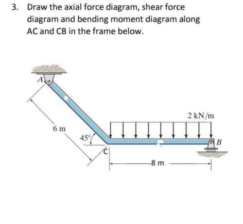
Answered 3 Draw The Axial Force Diagram Shear Bartleby

4 5 Practice Problems Learn About Structures

Draw Axial Force Shear Force And Bending Moment Diagrams For The Beam Shown Below Demonstrate Sing Convention And All The Calculations Study Com
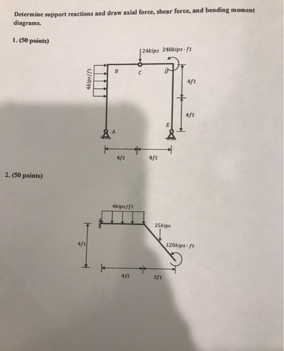
Solved Determine Support Reactions And Draw Axial Force Chegg Com

2 2 Axial Force Diagram Graphic Ex 2 2 Part Ii Youtube
1
0 Response to "40 how to draw axial force diagram"
Post a Comment