39 d8 tanabe sugano diagram
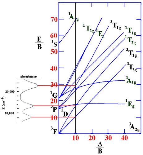
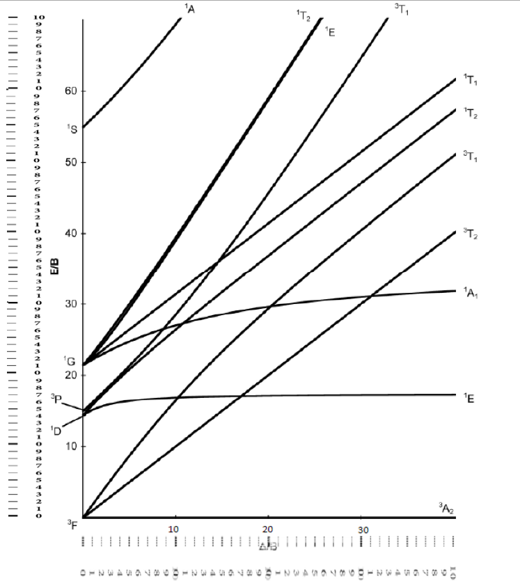
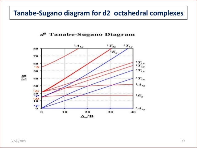
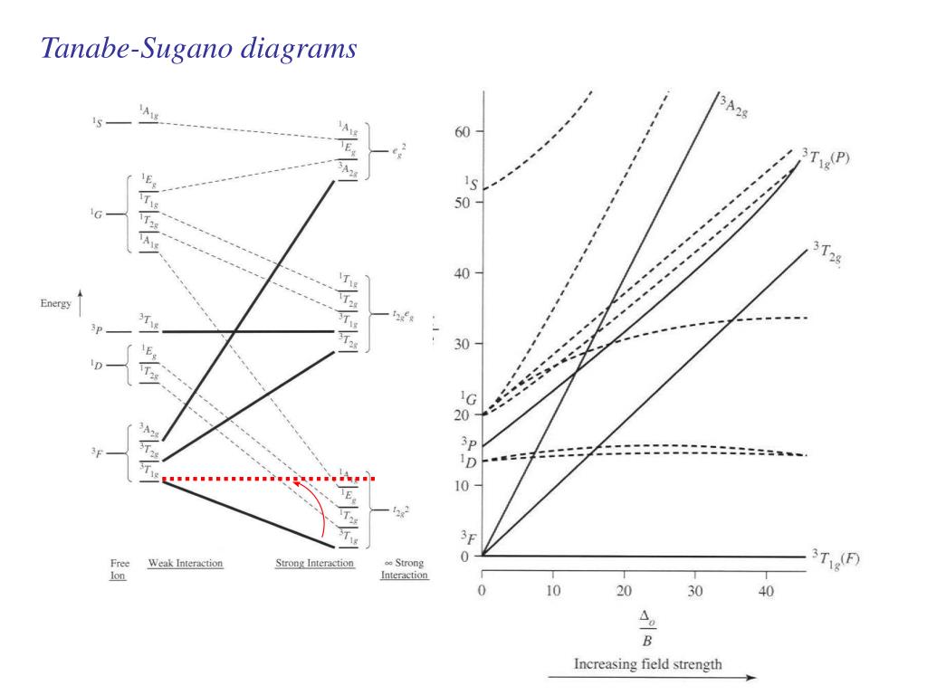
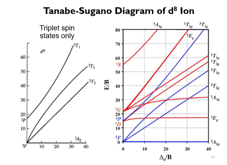
1 Aug 2021 — English: The Tanabe–Sugano diagram for a d8 transition metal ion. The energies are calculated using a Racah C = 4.5 B, and only selected states ... Lecture 4 May 11: Tanabe Sugano Diagrams A Tanabe-Sugano (TS) diagram plots the energy dependence of the various ligand field states (or terms) with field strength. The strength of the ligand field is defined by Dq, which is related to the octahedral crystal field splitting by 10Dq = ∆o. The energy of the state is given by E.
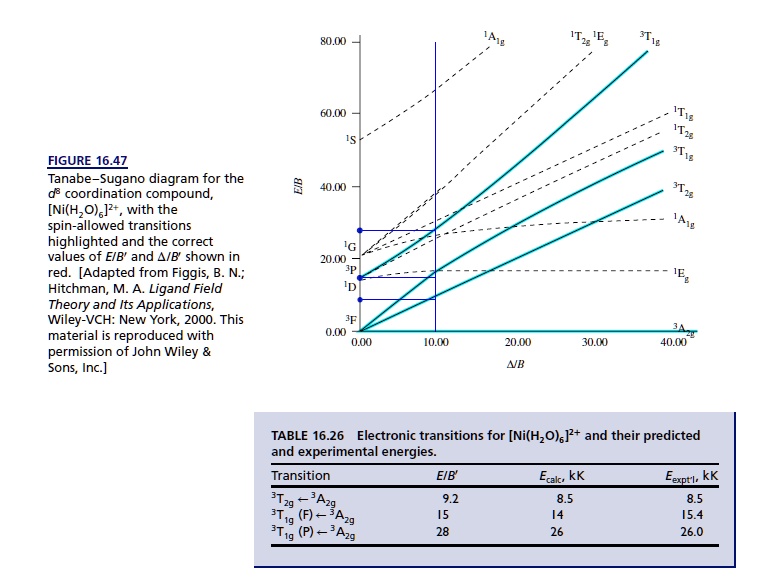
3 Tanabe-Sugano Diagrams The questions for this section are worth 4 points each. 1.For a nickel(II) complex three bands are observed at energies of 8000, 13200, and 22800 cm 1. what is the value of o?Shown below is the Tanabe-Sugano diagram for the d8 case. 2.Using the values from the preceding question, what is the approximate value of o/Bthat is ...

D8 tanabe sugano diagram
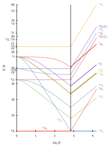
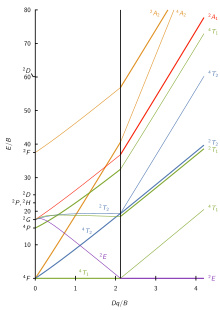
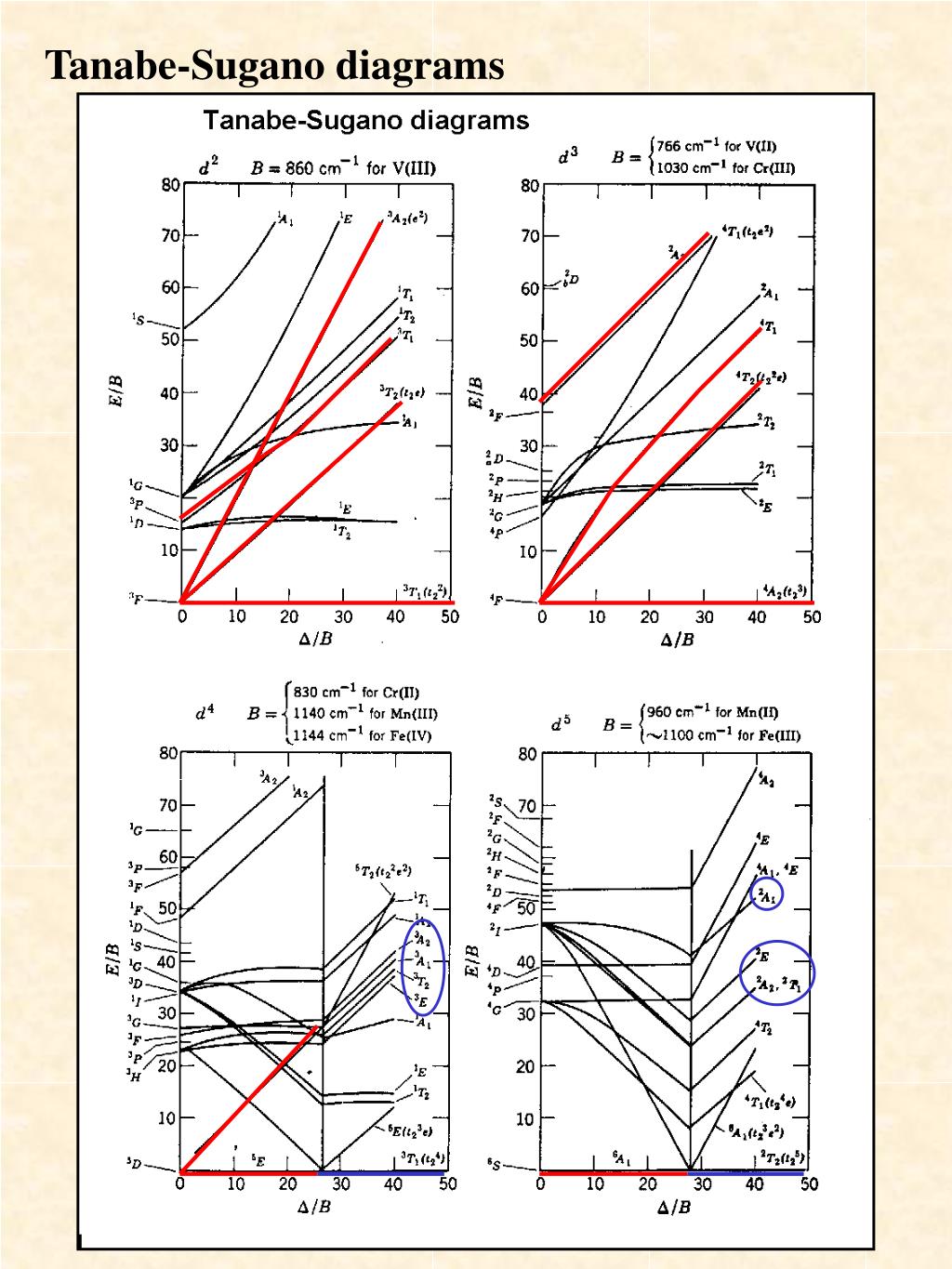
Notes on d7 Tanabe-Sugano Diagram!The d 7 diagram, like all such diagrams for configurations that may be either high spin or low spin, has a perpendicular line near the middle marking the change in spin state. "To the left of the line (low field strength, high spin), the ground state is 4T 1, emerging from the free-ion 4F term. d8 Tanabe-Sugano diagram. A Tanabe-Sugano diagram of the spin-allowed and some forbidden transitions for octahedral d 8 and tetrahedral d 2 complexes is given below. spin-allowed transitions Solid lines 3 T 1g (P) ← 3 A 2g Green 3 T 1g (F) ← 3 A 2g Blue 3 T 2g (F) ← 3 A 2g Red Certain Tanabe–Sugano diagrams (d 4, d 5, d 6, and d 7) also have a vertical line drawn at a specific Dq/B value, which is accompanied by a discontinuity in the slopes of the excited states' energy levels.This pucker in the lines occurs when the identity of the ground state changes, shown in the diagram below. The left depicts the relative energies of the d 7 ion states as functions of ...
D8 tanabe sugano diagram. 15 Aug 2020 — Tanabe-Sugano diagrams are used in coordination chemistry to predict electromagnetic absorptions of metal coordination compounds of ...D6 Tanabe-Sugano diagram: d7 ...D2 Tanabe-Sugano diagram: d3 ...Racah Parameters · Parameters · Diagrams · How to use the Diagrams Since cobalt is in the ninth column of the Periodic Table, it must be a d. 7 complex so we can use the d. 7 Tanabe-Sugano diagram from the last slide.22 pages d2, d8 systems: Figure 9. Qualitative correlation diagram for d2 octahedral and d8 tetrahedral complexes. Buy the complete book with TOC navigation,.40 pages The baseline in the Tanabe-Sugano diagram represents the lowest energy or ground term state. The d 2 case (not many examples documented). The electronic spectrum of the V 3+ ion, where V(III) is doped into alumina (Al 2 O 3), shows three major peaks with frequencies of: ν1=17400 cm-1, ν2=25400 cm-1 and ν3=34500 cm-1.
d2Tanabe-Sugano Diagram E / B ∆o/ B 3F 3P 3T 1g (3P) 3A 1g 3T 2g (3F) 3T 1g ~15B ~∆o ~∆o E1 E2 E3 E is the energy of the excited state relative to the ground state B is the Racah parameter for e–-e–repulsion The example on page 427 of your text shows how to use this chart to fit the experimental data (E1, E2, and E3) for [V(OH2)6]3+to ... In this video we will determine the values of 10Dq and B for a Ni(II) complex in Oh symmetry from its electronic absorption spectrum and the d8 Tanabe Sugano... Download scientific diagram | Tanabe-Sugano diagram for the d 8 electron configuration in the octahedral crystal field. The notation is the same as in Fig. Lecture 4 May Tanabe Sugano Diagrams A Tanabe-Sugano (TS) diagram plots the energy dependence of the various ligand field states (or terms) with field strength. The strength of the ligand field is defined by Dq, which is related to the octahedral crystal field splitting by 10Dq = ∆o. The energy of the state is given by E.
Tanabe–Sugano diagrams are used in coordination chemistry to predict absorptions in the UV, . d8 Tanabe-Sugano diagram. d8 electron configuration . A step-by-step tutorial on assigning the transitions in the UV-vis spectrum of a d7 system using a Tanabe-Sugano Diagram. d3 Tanabe-Sugano Diagram. 0. 0. 10 . d8 ν. 2. /ν. 1. Ratio. 0. 5. Certain Tanabe–Sugano diagrams (d 4, d 5, d 6, and d 7) also have a vertical line drawn at a specific Dq/B value, which is accompanied by a discontinuity in the slopes of the excited states' energy levels.This pucker in the lines occurs when the identity of the ground state changes, shown in the diagram below. The left depicts the relative energies of the d 7 ion states as functions of ... d8 Tanabe-Sugano diagram. A Tanabe-Sugano diagram of the spin-allowed and some forbidden transitions for octahedral d 8 and tetrahedral d 2 complexes is given below. spin-allowed transitions Solid lines 3 T 1g (P) ← 3 A 2g Green 3 T 1g (F) ← 3 A 2g Blue 3 T 2g (F) ← 3 A 2g Red Notes on d7 Tanabe-Sugano Diagram!The d 7 diagram, like all such diagrams for configurations that may be either high spin or low spin, has a perpendicular line near the middle marking the change in spin state. "To the left of the line (low field strength, high spin), the ground state is 4T 1, emerging from the free-ion 4F term.












0 Response to "39 d8 tanabe sugano diagram"
Post a Comment