41 vdo marine tachometer wiring diagram
Install them now. Refer to Diagram E. 12. Connect the black wire from the tachometer to the black wire of the shielded cable (GROUND). 13. Connect the green wire from the tachometer to the white wire in the shielded cable (TACH SIGNAL). 14. Finally, connect the red wire from the tachometer to the red wire in the shielded cable. The remaining white Jul 31, 2021 · Vdo Marine Tachometer Wiring Diagram – Data Wiring Diagram Schematic – Tachometer Wiring Diagram. Wiring Diagram contains several detailed illustrations that present the relationship of varied things. It consists of guidelines and diagrams for various types of wiring techniques as well as other items like lights, home windows, etc.
Description : Black Yanmar Marine Engine Instrument Panel, White Gauges 10″ X with regard to Boat Gauge Wiring Diagram For Tachometer, image size 2338 X 1700 px, and to view image details please click the image. Description : Vdo Gauges Wiring Diagrams And Boat Tach Diagram E Z Go Golf Cart regarding Boat Gauge Wiring Diagram For Tachometer ...

Vdo marine tachometer wiring diagram
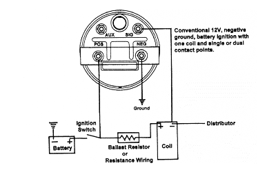
VDO Tachometer Installation Instructions Subject: Revision: VDO Programmable Tachometer Installation Instructions 10/05/04 B Revision Date: Standards No. 5000041-02 Page 2 of 4 Date Originated: 3.0 Wiring the Tachometer 1. Disconnect vehicle battery ground before performing this wiring. Prepare insulated 1/4"(6.3mm) spade terminals for use. Diagram E Proper wiring of the VDO Programmable Tachometer with typical ignition systems ˘ˇˆ ˙˘ ˝ˇ ! "˙ Diagram F Fine adjustment of the VDO Tachometer when used with an alternator Compare the VDO Tachometer reading with that of a reference tachometer. Adjust the potentiometer on the back of the tach. When the VDO Tachometer reading A Vdo Marine Tachometer Wiring Diagram can be really a compacted conventional pictorial representation of a electric circuit. It shows that the components of the circuit because simplified shapes, and also the power and signal connections in between the apparatus. vdo tach wiring instructions - wiring library •, size.
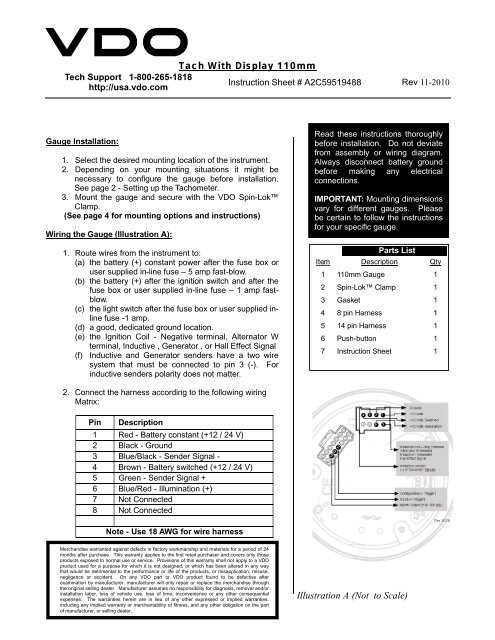
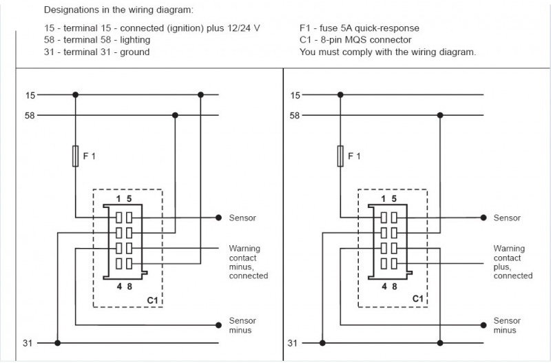
Vdo marine tachometer wiring diagram. Vdo Gauges Wiring Diagrams - Page 3 - Wiring Diagram And Schematics vdo marine fuel gauge wiring diagram best of gauge sending. Ford Fusion Relay And Fuse Box Diagram - List Of Schematic ford escape fuse box location just wiring data rh ag skiphire co uk. VDO Spin-Lok™ Clamp or mounting bracket 1 5. 4in (4in (100mm)) 5000RPM tachometer. Cockpit International Gen II 4,000 RPM Tachometer with Hourmeter. Use with Alternator or Generator Sender Signals. Tachometer, without Display 13 GB 14 Connector set, 8-pin A2C59510850 30 - terminal 30 - steady-state plus 12 V 15 - terminal 15 - connected (ignition) plus 58 - terminal 58 - lighting 31 - terminal 31 - ground Designations in the wiring diagram: 8-pin connection F1 - fuse 5A quick-response C1 - 8-pin MQS connector You must comply with the ... shown in Diagram C. You may also mount the tachometer using an optional VDO mounting bracket and nuts. I. Mounting the Tachometer 1. Prepare insulated ¼" spade terminals for use with the tachometer. Make sure all wires are long enough to reach the necessary positive and negative terminals and any wires from the sensor. 2. Connect the wire from pin #4 to a switched +12 volt
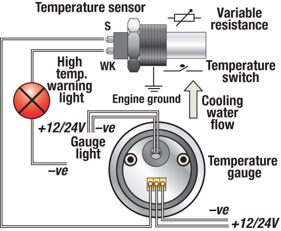
Connect the shield and ground wire to the ground post on the MSD box or the main MSD ground. Connect the power wire to the ignition terminal on the MSD box, and the signal wire to the tach output terminal on the MSD box. At the tach end, connect the red wire to power, the green wire to signal, and the black wire to ground (see Diagram I on Page 5). VDO Cylinder Head Temperature Gauge Handlebar/Fairing Mount - 2009. VDO Resitive Gauge wiring Instructions - 2009. Veratron Flex Gauge 52mm NMEA2000 12/24v. ViewLine 52mm Wiring Diagram (2014) ViewLine Standard Resistive Gauges 52mm Installation Sheet (2014) Viewline Temperature Gauges 12/24 Volt (2011) Viewline Temperature Gauges 52mm (2008) A Vdo Marine Tachometer Wiring Diagram can be really a compacted conventional pictorial representation of a electric circuit. It shows that the components of the circuit because simplified shapes, and also the power and signal connections in between the apparatus. vdo tach wiring instructions - wiring library •, size. Diagram E Proper wiring of the VDO Programmable Tachometer with typical ignition systems ˘ˇˆ ˙˘ ˝ˇ ! "˙ Diagram F Fine adjustment of the VDO Tachometer when used with an alternator Compare the VDO Tachometer reading with that of a reference tachometer. Adjust the potentiometer on the back of the tach. When the VDO Tachometer reading
VDO Tachometer Installation Instructions Subject: Revision: VDO Programmable Tachometer Installation Instructions 10/05/04 B Revision Date: Standards No. 5000041-02 Page 2 of 4 Date Originated: 3.0 Wiring the Tachometer 1. Disconnect vehicle battery ground before performing this wiring. Prepare insulated 1/4"(6.3mm) spade terminals for use.














0 Response to "41 vdo marine tachometer wiring diagram"
Post a Comment