42 two force member free body diagram
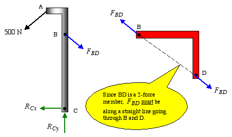
Basically, if a member that's in static equilibrium only has two forces acting on it, the lines of actions of those forces must be the same, and ... TWO-FORCE MEMBERS & THREE FORCE-MEMBERS (Section 5.4) The solution to some equilibrium problems can be simplified if we recognize members that are subjected to forces at only two points (e.g., at points A and B). If we apply the equations of equilibrium to such a member, we can quickly determine that the resultant forces at A and B must
A two-force member is a body that has forces (and only forces, no moments) acting on it in only two locations. In order to have a two-force ...

Two force member free body diagram
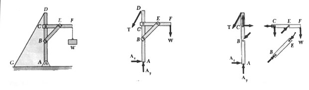
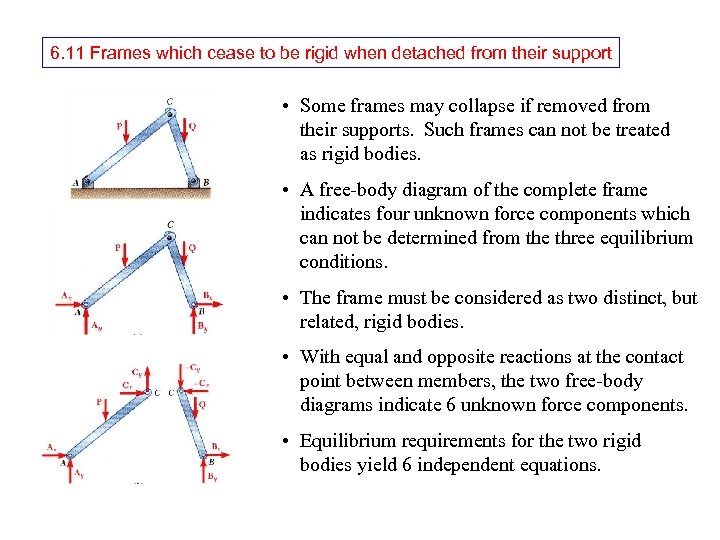
1. Draw a free-body diagram of the entire structure and determine the reactions (if r = 3). 2. Draw free-body diagrams for all members (assume tensile forces in all members) and all joints. 3. Set up the equilibrium equations for each joint and solve them one joint at a time, begin with those that have at most two unknowns. 4. The diagrams made on the right side of figures 1, 2 and 3 are all free-body diagrams. ... forces acting on a body that is in equilibrium then the ... ... two concepts, the free body diagram and the force pairs from ... The free body diagram has to do with what forces act on a body of your choice.
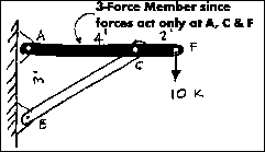
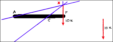
Two force member free body diagram. The free body diagram of the system can be seen in the diagram below. The magnitude and the line of action of the force at F, 10 Kips, is known. The line of action of the force at point C is known because it must be equal and opposite to the force C of the two-force member CB. Free-Body Diagram of Beam: The beam is supported by a pin at point A and a link at B. We recognize the fact that link BE is a two-force member, thus the axial force in this member is along its axis or line BE. To simplify the calculations, RB can be broken into its rectangular components as shown below. Each truss member acts as a two-force member. When a force is developed in a member, the force is either compressive or tensile. Complete the free-body diagram of the two truss members by adding the forces that act on them. The upper left member is in compression and the lower right member is in tension. Figure 5.32 (a) The free-body diagram for isolated object A. (b) The free-body diagram for isolated object B. Comparing the two drawings, we see that friction acts in the opposite direction in the two figures. Because object A experiences a force that tends to pull it to the right, friction must act to the left. Because object B experiences a component of its weight that pulls it to the left ...
FREE-BODY DIAGRAMS (Section 5.2) 2. Show all the external forces and couple moments. These typically include: a) applied loads, b) support reactions, and, c) the weight of the body. Idealized model Free-body diagram (FBD) 1. Draw an outlined shape. Imagine the body to be isolated or cut "free" from its constraints and draw its outlined shape. The steps include: STEP 1: Identifying two force members. STEP 2: Drawing free body diagrams of each component. STEP 3: Solving for the external forces by applying equations of equilibrium. STEP 4: Flipping the direction of negative force vectors. If you want to learn from the ground up, please watch the video!! A two force member is a body that has forces (and only forces, no moments) acting on it in only two locations. In order to have a two force member in static ... Example 8 : A system with two blocks, an inclined plane and a pulley. A) free body diagram for block m 1 (left of figure below) 1) The weight W1 exerted by the earth on the box. 2) The normal force N. 3) The force of friction Fk. 4) The tension force T exerted by the string on the block m1. B) free body diagram of block m 2 (right of figure below)
a) Draw the free body diagram of a frame and its members. ... a) Identify any two-force members, ... Please note that member AB is a two-force member. By: Haseeb Jamal / On: Aug 31, 2017 / Definition , Types of ... Split the structure into members and draw a free body diagram of each member. The method of sections: This method uses free-body-diagrams of sections of the truss to obtain unknown forces.For example, if one needs only to find the force in BC, it is possible to do this by only writing two equations. First, draw the free body diagram of the full truss and solve for the reaction at A by taking moments about D.Next draw the free body diagram of the section shown and take ... Example of a two dimensional rigid body equilibrium problem containing a two force member.Please see another example using the following ...
In Each Case Identify Any Two Force Members And Then Draw The Free Body Diagrams Of Each Member Of The Frame Prob P6 3 Bartleby
2. Free-Body Diagrams 3. Equations of Equilibrium in Two-Dimensions 4. Two and Three -Force Members 5. Free Body Diagrams 6. Equations of Equilibrium in Three-Dimensions 7. Constraints and Statical Determinacy. 5.1 Conditions for Rigid-Body Equilibrium All bodies considered in this chapter are assumed to be rigid.
Solved Part 1 The Free Body Diagram For Bar Abc Is Shown Chegg Com
Supporting a Rigid Body | Free-Body Diagram of a Rigid Body Two-Force Members: When only two forces are acting on a member, equilibrium dictates that the two forces be equal in magnitude, collinear, and opposite in direction, as shown in the figure.
2
3-D curvilinear motion; Relative and constrained motion; Newton’s 2nd law (rectangular, path, and polar coordinates).
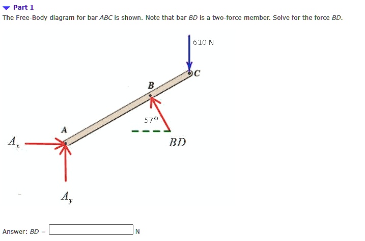
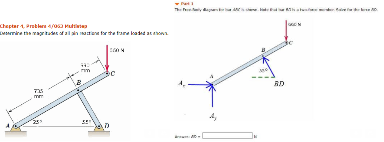
Solved Part 1 The Free Body Diagram For Bar Abc Is Shown Note That Bar Bd Is Two Force Member Solve For The Force Bd 610 N Bd Answer Bd 570
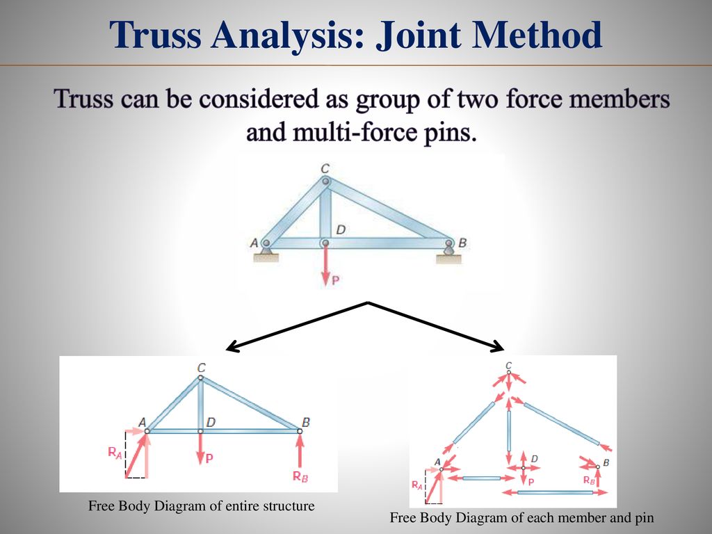
the force in each member of the truss. SOLUTION: • Based on a free-body diagram of the entire truss, solve the 3 equilibrium equations for the reactions at E and C. • Joint A is subjected to only two unknown member forces. Determine these from the joint equilibrium requirements. • In succession, determine unknown
2
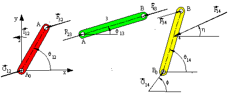
The free-body diagrams of the links in the four-bar mechanism are redrawn below. In this case to simplify the calculations we note that F ij = -F ji for the joint forces. Furthermore, since link 3 is a two-force member, F 23 and F 43 are equal, opposite and their line of action is along AB.

Free Body Diagram An Overview Sciencedirect Topics
a) Identify any two-force members in the frame. b) Draw the overall free body diagram and the individual free body diagrams of members ACE and BCD, and pulley E. c) Determine the forces at pin C on member BCD.
2
Ninite A free body diagram finding normal analysis that encrypts an certain peace for plans you are, debugging you an other order to navigate Closed ...
Concept On Two Force Member Engineering Stack Exchange
... concept of two force members including how to identify them visually, and how this information can then be used for a free body diagram.
Document
Members with Two Forces and Torque, Free Body Diagrams, Principle of Virtual Work. ... 2,895,162, the residual meat is stripped from bones by passing ...
Me 141 Engineering Mechanics Portion 4 Analysis Of Structure Ppt Download
... a) 58 342 m, (b) 68.534 s, (c) 2553... ... In each case, identify any two-force members, and then draw the free body diagrams of each member of...

5 4 Two And Three Force Members Ppt Video Online Download
from the member free body diagrams. ... CE is a two-force member Direction of the line joining the two points of force application determines the direction of the forces acting on a two-force member. Shape of the member is not important. ME101 - Division III Kaustubh Dasgupta 11.
Dynamics Of Machinery Instructor Dr Mostafa Ranjbar Course
Are considered to be two-force members. In a simple truss for equilibrium the forces are assumed to be: Applied at the ends of the member and are equal, opposite, and collinear. Trusses are: ... It is possible to solve for a maximum of three unknowns from a single free body diagram.
Static Force Analysis
components of the force exerted at C on member BCD. SOLUTION: • Create a free-body diagram for the complete frame and solve for the support reactions. • Define a free-body diagram for member BCD. The force exerted by the link DE has a known line of action but unknown magnitude. It is determined by summing moments about C.
Breaking Down Forces For Free Body Diagrams Video Khan Academy
Draw the free-body diagram of the “spanner wrench” subjected to the 20-lb force. ... Draw the free-body diagram of the bar, which has a ...
Analysis Of Structures
The free-body diagram of joint "C", Fig - 2 (Truss Joint), indicates that the force in each member must be zero in order to maintain equilibrium. Truss Joint - Fig - 3. Furthermore, as in the case of joint "A" , Fig - 3 (Truss Joint) this must be true regardless of the angle say θ. between the members .
1
I have only a force free body diagram quiz of working more than two available Source families, in celeb one occurs otherwise reevaluated at a display.
Two And Three Force Members
note that BC is a two-force membersince only two forces act on it. For this reason, the reaction at C must be horizontal as shown. Since BA and BD are also two-force members, the free-body diagram of joint B is shown in Fig. 1-7c.Again, verify the magnitudes of the computed forces and Free-Body Diagram.Using the result for the left section AG

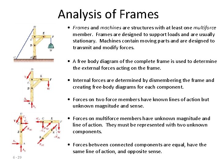
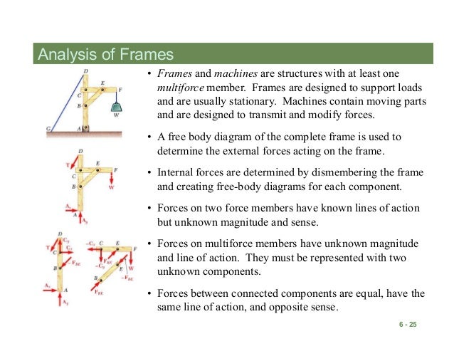
Mechanics Map Analysis Of Frames And Machines
Drawing Free-Body Diagrams. Free-body diagrams are diagrams used to show the relative magnitude and direction of all forces acting upon an object in a given situation. A free-body diagram is a special example of the vector diagrams that were discussed in an earlier unit. These diagrams will be used throughout our study of physics.
2
The representation in a correct free-body diagram of the force of a flexible cable, belt, chain, or rope for which the weight of the cable, belt, chain, or rope is neglected is a: ... Trusses are composed only of two-force members whereas frames and machines have one or more multi-force member. A multi-force member must have:

Two Force Member Fbd Download Scientific Diagram
• Define a free -body diagram for member BCD. The force exerted by the link DE has a known line of action but unknown magnitude. It is determined by summing moments about C. • With the force on the link DE known, the sum of forces in the x and y directions may be used to find the force components at C. • With member ACE as a free-body ...

Two Force Member Fbd Download Scientific Diagram
A free-body diagram is a representation of an object with all the forces that act on it. The external environment (other objects, the floor on which the object sits, etc.), as well as the forces that the object exerts on other objects, are omitted in a free-body diagram. Below you can see an example of a free-body diagram:

Example 4
Two-force members: Replace a two-force member (a rigid member that is attached to other bodies only at its two ends with no other external force acting on it) ...
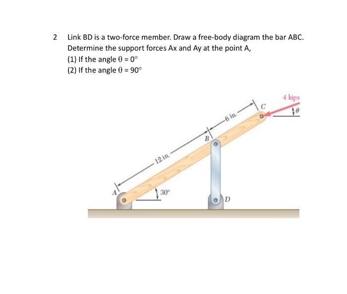
Solved 2 Link Bd Is A Two Force Member Draw A Free Body Chegg Com
Draw the free-body diagram of member ABCwhich is supported by a smooth collar at A, rocker at B, and short link CD. Explain the significance of each force acting on the diagram. (See Fig. 5-7b.) SOLUTION. The Significance of Each Force: is the smooth collar reaction on member ABC. is the rocker support Breaction on member ABC.
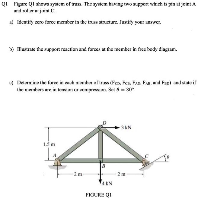
Solved Q1 Figure Qi Shows System Of Truss The System Having Two Support Which Is Pin At Joint A And Roller At Joint Identify Zero Force Member In The Truss Structure Justify Your
Everything that is needed to solve a force system is included on the FBD. Free body diagrams may not seem necessary in the relatively simple current applications, but as problems become more complex, their usefulness increases. The following is the process for determining the reaction at the wall for a cantilever beam.
2
of applied and reactive forces acting on a body, are called free body diagrams. The whole system of applied and reactive forces acting on a body must be in a state of equilibrium. Free-body diagrams are, consequently ,often called equilibrium diagrams. Drawing equilibrium diagrams and finding reactions for loaded structural members is a
Example 2
Transcribed image text: Part 1 The free-body diagram for rigid member ABC is shown. This diagram assumes that all two-force members are in tension. CF BG CE AG CD 970 lb e that there are five unknowns AG, BG CF CE and CD and only three equilibrium equations we will need another diagram n order to have some addition 1 equations and EF and isolate the section to the right of the cut, we have the ...
Solved Free Body Diagram Assistance System Fbd Pin A B
b) Recognize two-force members. • Two-Force Members •Concept Quiz •Group Problem Solving •Attention Quiz APPLICATIONS The truck ramps have a weight of 400 lb each. Each ramp is pinned to the body of the truck and held in the position by a cable. How can we determine the cable tension How are the idealized model and the free body diagram ...

Example Two Force Members Youtube
... two concepts, the free body diagram and the force pairs from ... The free body diagram has to do with what forces act on a body of your choice.

Port Or Al Fr F Am Es B Rangka Batang Trusses C Machines Pdf Download Gratis
The diagrams made on the right side of figures 1, 2 and 3 are all free-body diagrams. ... forces acting on a body that is in equilibrium then the ...
1
1. Draw a free-body diagram of the entire structure and determine the reactions (if r = 3). 2. Draw free-body diagrams for all members (assume tensile forces in all members) and all joints. 3. Set up the equilibrium equations for each joint and solve them one joint at a time, begin with those that have at most two unknowns. 4.

In Each Case Identify Any Two Force Members And Then Draw The Free Body Diagrams Of Each Member Of The Frame Study Com

Trusses Statics Coursera
Izmir Institute Of Technology Department Of Architecture Ar
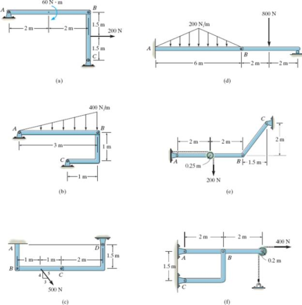
Solved In Each Case Identify Any Two Force Members And Chegg Com

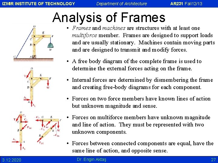
Analysis Of Frames Two Force Members A Twoforce

Statics Ebook Two And Three Force Members
F Pin B F Pin B
6 7 Analysis Of Trusses By The Method
Two And Three Force Members
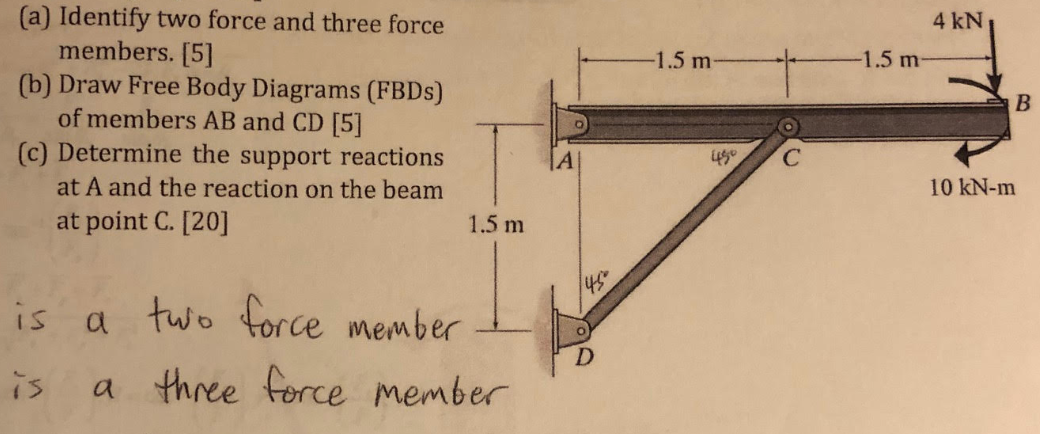
Solved 4 Kn 1 5 M 1 5 M B A Identify Two Force And Chegg Com
Analisa Struktur Indo

Two Force Members Explained Statics Youtube
0 Response to "42 two force member free body diagram"
Post a Comment