42 current sensing relay circuit diagram
Relay is an electro-mechnical device which acts as a switch. DC electrical current is used to energize the relay coil which opens or closes the contact switches. Internal circuit of a single channel 5V relay consists of normally open contacts, normally closed contacts and a coil. Description: Cargo Voltage Sensing Split Charge Relay 140 Amp with regard to Voltage Sensing Relay Wiring Diagram, image size 764 X 613 px, and to view image details please click the image.. Truly, we also have been remarked that voltage sensing relay wiring diagram is being just about the most popular field at this time.
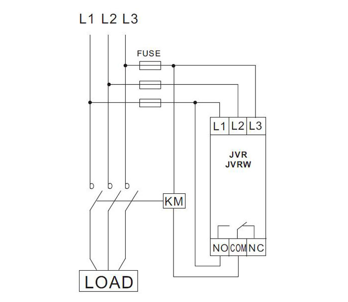
The coil gets de-energized by sensing excess current in the load due to overload. The temperature of the motor winding can be estimated using the motor armature thermal model, electronic overload protection relay by measuring motor current. ... Thus, the relay operates and opens the circuit breaker so as to trip the circuit.
Current sensing relay circuit diagram
Photocell Circuit Diagram. ... This activates the relay circuit and so the siren starts to shout. ... This article has provided the detailed concept of photocell working, its types, photocell sensor, uses, circuit, and applications. In addition, by conducting a photocell experiment, ... A general Relay is a mechanical switch. Its contact is closed when a current flows through a coil. On the circuit diagram below is a simple basic circuit. You will understand the working of a relay. A smaller voltage (V1) is the maximum voltage that the coil can get it. There is a lower-current I1 flow through R-resistor. Relay current I = 12/400 = 0.03 or 30 mA. Also the Hfe of any standard low signal transistor may be assumed to be around 150. Applying the above values in the actual equation we get, R = (Ub - 0.6) × Hfe ÷ Relay Current. R = (12 - 0.6)150/0.03 = 57,000 Ohms or 57 K, the closest value being 56 K.
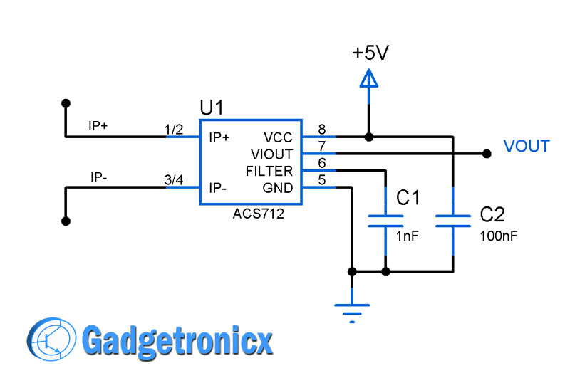
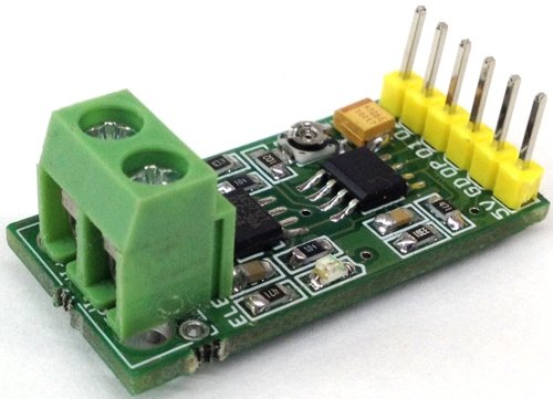
Current sensing relay circuit diagram. Voltage Sensing Vsr Relay Wiring Diagram 19.08.2018 19.08.2018 3 Comments on Vsr Relay Wiring Diagram Digital Voltage Sensing Relay (DVSR) 12/24V Part # A Twin Outboard Engine, Three Battery Banks with Motorized VSR Part # NARVA BL VOLTAGE SENSITIVE RELAY 12V VSR ISOLATOR A and automatically connect/disconnect the appliance or circuit at the ... Internal Circuit Diagram for Single Channel Relay Module The circuit on the PCB is quite simple. The extra components apart from the relay are there since it would not be possible to drive the relay directly from the pins of a microcontroller. digital logic or a sensor. Arduino uno interfacing with acs712 current sensor circuit diagram is given below. The circuit is universal and all the above three codes for different versions of acs712 current sensor can work with the same circuit given below. Circuit diagram of the IR motion sensor relay switch is shown in Fig. 2. It is built around a PIR motion sensor module (connected across CON2), MOSFETs BS170 (T1) and IRF9540 (T2), rectifier diode 1N4007 (D1) and a few other components. Pir Sensor Mohan S Electronics Blog.
When a signal from an Infrared PIR Sensor module comes to the circuit. It is a 3V peak voltage. Then, this voltage flows to the base of Q1 through R1-current limiting for the transistor. Now Q1 runs, the current can flow from the 12V to a relay coil. The RY1 pulls contact C to NC. Next, the siren alert with a lot louder. At the same time, LED ... The relay consists of two unrelated circuits - control circuits A1 and A2 and controlled circuit 1, 2 and 3. There is a metal core between A1 and A2. An anchor (2) will be attracted to it if an electric current is applied to it. 1, 3 - fixed contacts. Simple SCR Circuits. In this post we will learn how to build a few SCR applications circuits such as battery charger, code oscillator, rain alarm, automatic night lamp etc. An SCR or a silicon controlled rectifier is a semiconductor device which conducts a relatively larger voltage and current across its anode cathode terminals in response to a ... His circuit in post #10 using 2 relays is a MUCH better solution as the relays can be located close to the motor and the wire to the switches only needs to carry the small current required to operate the relay coils. The extra cost of thick wire may well be more than the cost of two relays. Les.
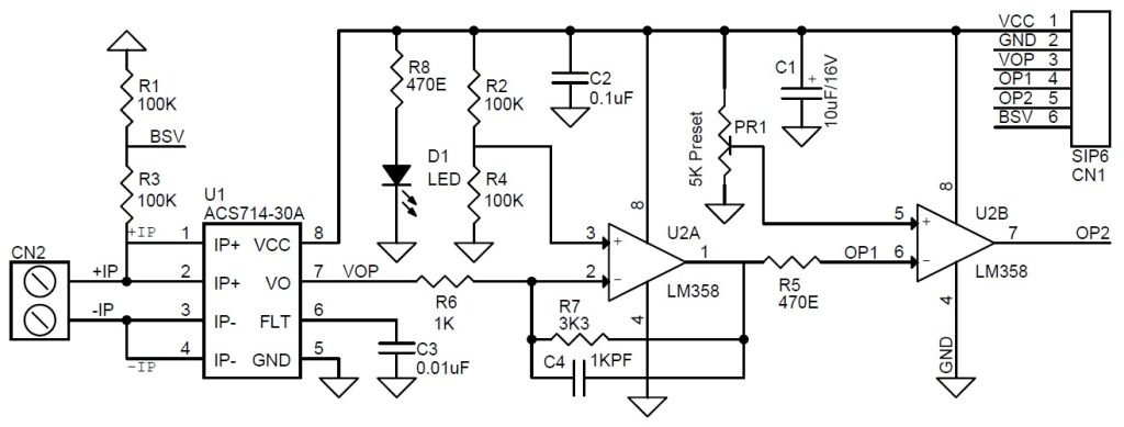
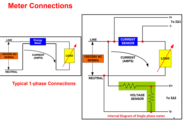
One Channel Relay: a) Relay module and b). Circuit diagram 3.2. Current Sensor Module In this proposal, we used the ACS712 Current sensor module 30 A. This sensor is an economical solution to measure AC or DC current, it works with a Hall effect sensor that detects the magnetic Ground-fault relays for solid and resistance-grounded systems - Bender's RCM, RCMA, and RCMS series relays monitor leakage current in AC (single and three phase) and DC power and control circuits. Available in single-channel and multi-channel options. LifeGuard® and MarinaGuard® integrated panels are ground-fault interrupters (GFI) for a wide variety of applications. Light Sensor Circuit Working Operation. The light sensor circuit is an electronic circuit designed using (light sensor) LDR, Darlington pair, relay, diode, and resistors which are connected as shown in the light sensor circuit diagram. A 230v AC supply is provided to the load (in this case, the load is represented with a lamp). 14+ Earth Leakage Relay Circuit Diagram. Some optional functions do not need to be cabled). To manually test trip circuit, by pressing continuously for 5 sec, the relay trips and meter indicates to manually reset the relay. Earth Leakage Relay Wikipedia - The Earth Images Revimage.Org from cromptoncanada.com Earth leakage…
3
Motion Activated PIR Relay Circuit. The submit reveals an easy motion activated PIR relay circuit widely available for activating lights only in the occurrence of a human, as a result conserving important electric power. Following is an ordinary circuit that activates a relay when a living being (a human) is detected by the PIR sensor.
Faq Functional Devices Inc
Fig. 2: Block diagram for Touchless Doorbell. Fig. 3: Circuit diagram of touchless doorbell. NE556 is a dual NE555 timer IC capable of producing precise time delays or oscillation. It has two independent timers. One timer is configured as an astable multivibrator (built around pins 8 through 13), which is used to drive the IR sensor circuit ...
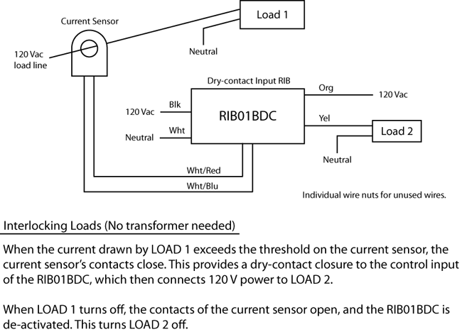
Current Sensor Switch Circuit Gadgetronicx
10+ Ldr Circuit Diagram With Relay. Also, we will not demonstrate only one circuit but instead, three circuit will be put under the microscope. Below is the circuit diagram of this light sensing street light project. The top circuit diagram shows an LDR (light sensor … from www.afiata.com. Control the relay by programming the pin to low or high.

Iot Based Electricity Energy Meter Using Esp32 Blynk
Tracing current flow through the circuit is also easier because the power is at the top and the ground is at the bottom of each page. • Printed in Color Because the diagrams are printed in color, identifying the wires shown on the wiring diagram in the vehicle harness or at the connectors is a lot easier.

In Depth Interface Two Channel Relay Module With Arduino
View Live Inventory 360 Images Online. This is a LOW Level 5V 2-channel relay interface board and each channel needs a 15-20mA driver current. Pin On Creative How to set up a 5v relay on the arduino tutorial circuit basics 4 channel module wiki 2 aptofun working for mc easyeda. 5v relay board circuit diagram. […]
Refrigeration
Circuit Diagram using Hall Effect Sensor. ... However, when the relay switches, the current will be removed which will prompt the relay to switch again, and this may cause rapid chattering of the relay at the thresholds. To avoid this, a latching feedback will be necessary. Also make sure to add a 47uF/25V capacitor across base/emitter of the ...
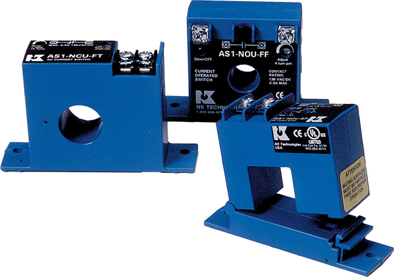
Current Sensing Switches Current Sensing Relays Nk Technologies
While Ice is controlled by the diode current If, the PC817 diode forward current If can be correctly determined through the relationship curve of PC817's Vce and If. Optocoupler PC817 application circuit diagram (4) TTL control signal input circuit of 12V DC motor composed of PC817.
Iopscience Iop Org
Every alarm circuit and control circuit is composed of a number of basic components connected together to achieve the desired performance. The following lists some common and simple alarm and control circuits diagrams to share different ideas for protecting your home/office and making your life more easier.

Low Current Relay Switch Circuit
The light sensor circuit is an electronic circuit designed using light sensor LDR Darlington pair relay diode and resistors which are connected as shown in the light sensor circuit diagram. This is the Best motion sensor light switch circuit diagram you can make this with a few components. The circuit uses an Op Amp as voltage comparator.

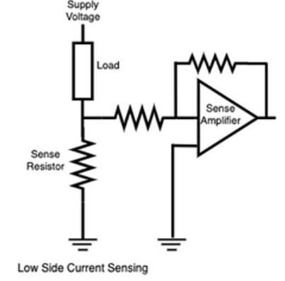
Fundamentals Of Current Measurement Part 2 Digikey
An overcurrent protection device (OCPD) is a piece of electrical equipment used to protect service, feeder, and branch circuits and equipment from excess current by interrupting the flow of current. Overcurrent protection simply means a fuse, breaker, or fusible link is used to protect the equipment, a circuit in the equipment, or the equipment ...

Switching 12vdc Led Indicator Lamp Through 12vdc Relay Leds And Multiplexing Arduino Forum
The circuit breaker has mechanisms to detect and prevent the formation of arcs in the circuit. Few other difference between relay and circuit breaker to keep in mind: A relay may be included in a Circuit breaker, but a circuit breaker is not included in the relay. A relay finds use to switch circuits with small currents, while a circuit breaker ...

Current Sensing Relay With Delay On Break For Dust Collection System Electrical Engineering Stack Exchange
Relay current I = 12/400 = 0.03 or 30 mA. Also the Hfe of any standard low signal transistor may be assumed to be around 150. Applying the above values in the actual equation we get, R = (Ub - 0.6) × Hfe ÷ Relay Current. R = (12 - 0.6)150/0.03 = 57,000 Ohms or 57 K, the closest value being 56 K.

The Basics Of Current Sensing Relays Ec M
A general Relay is a mechanical switch. Its contact is closed when a current flows through a coil. On the circuit diagram below is a simple basic circuit. You will understand the working of a relay. A smaller voltage (V1) is the maximum voltage that the coil can get it. There is a lower-current I1 flow through R-resistor.
Over Current Cut Off Power Supply Using Arduino Homemade Circuit Projects
Photocell Circuit Diagram. ... This activates the relay circuit and so the siren starts to shout. ... This article has provided the detailed concept of photocell working, its types, photocell sensor, uses, circuit, and applications. In addition, by conducting a photocell experiment, ...
Current Activated Switch Diywiki
Current Sensing Techniques How To Measure Current With Different Current Sensors

Ice Breaker Troubleshooting Current Relays 2012 09 03 Achrnews Achr News

Autonics Fx4 Counter Wiring With Direct Online Starter Proximity Sensor Diagram
Current Sensor Amplifier Over Current Switch Electronics Lab Com

Phase Failure Relay Definition Working Principle Advantages
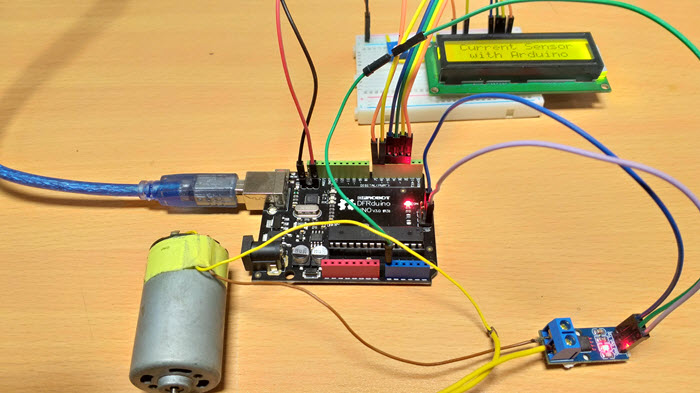
Interfacing Acs712 Current Sensor With Arduino Measure Current With Arduino Measuring Current With Arduino
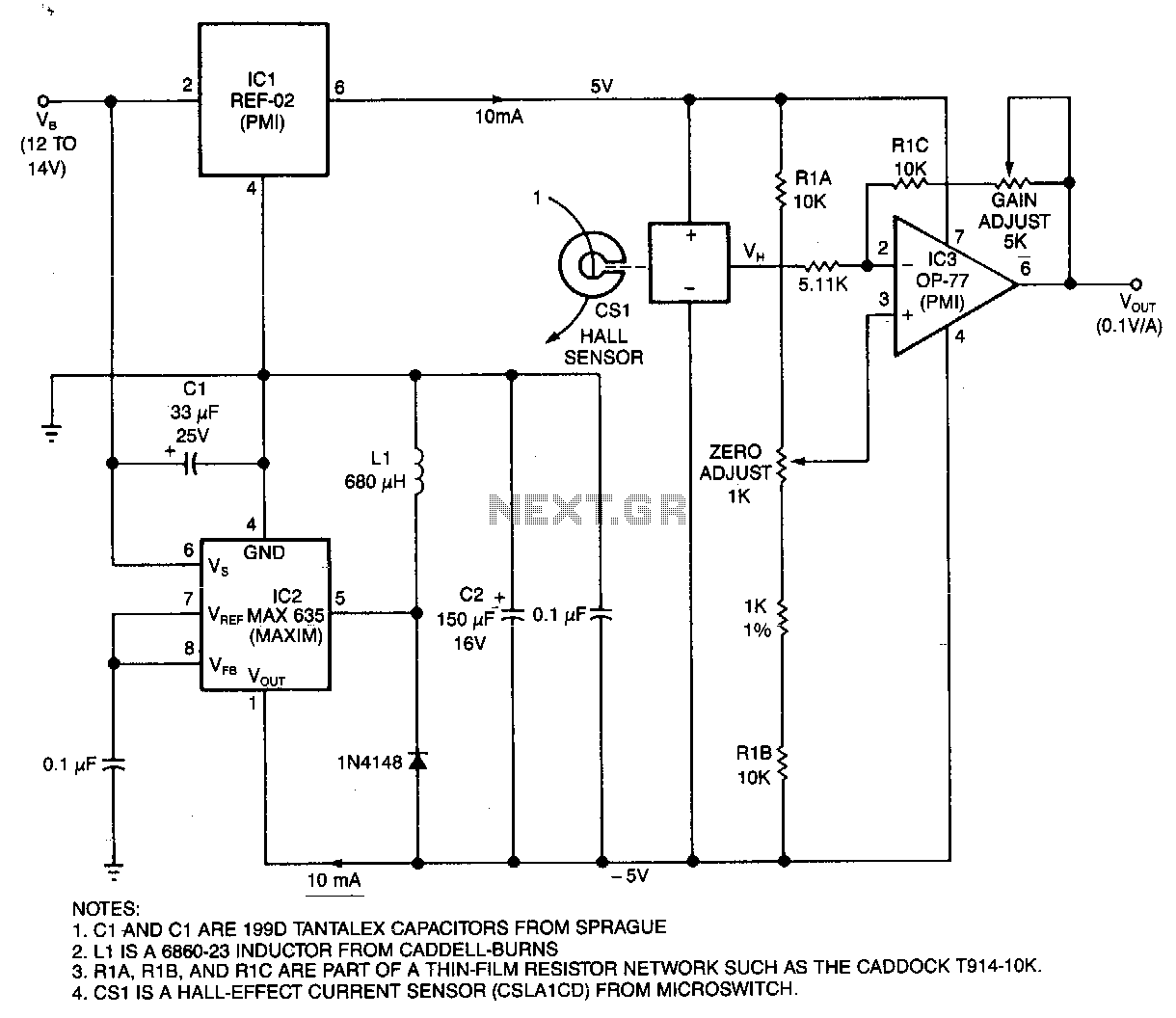
Current Monitor Under Hall Effect Circuits 13368 Next Gr

Amazon Com Current Sensing Switch Normally Open Current Sensing Relay Adjustable Ac 0 2a 30a Szc23 No Al Ch Model Industrial Scientific
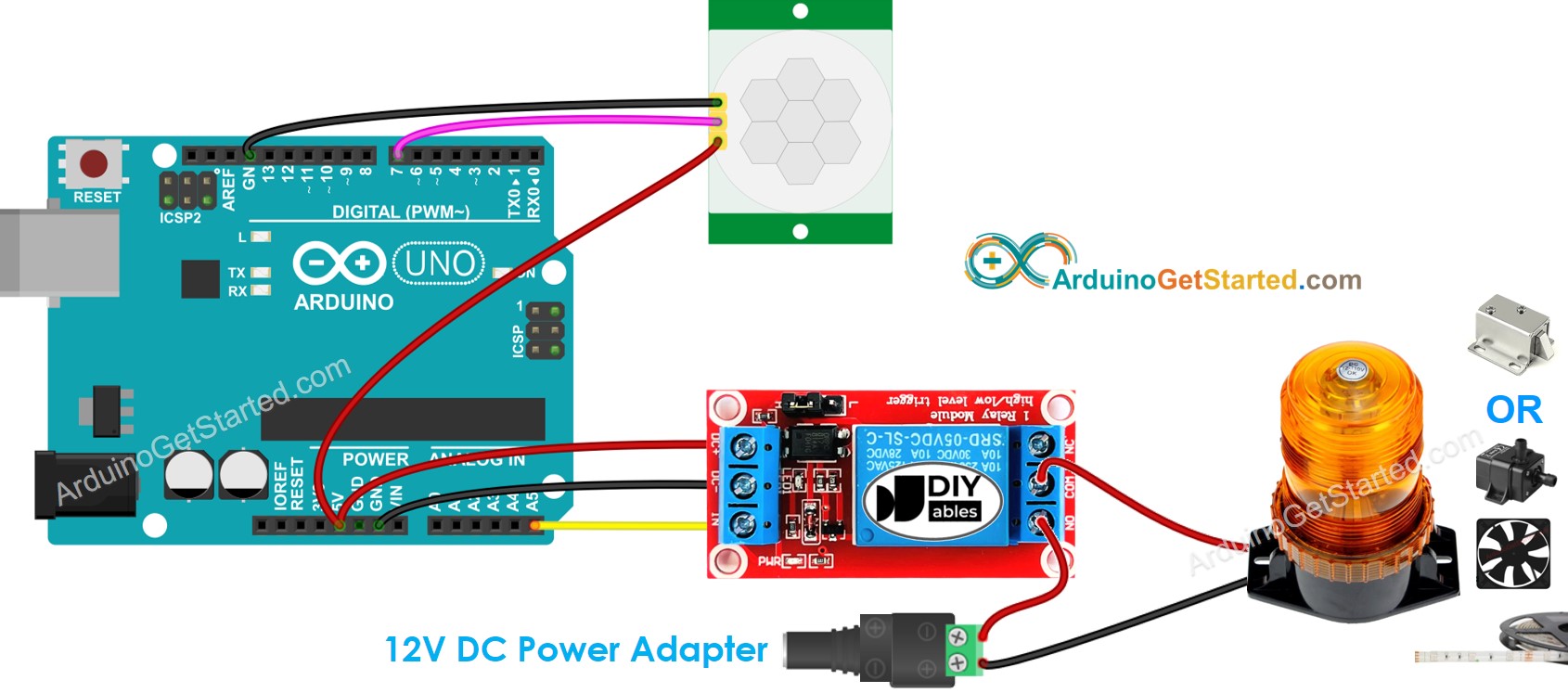
Arduino Motion Sensor Relay Arduino Tutorial
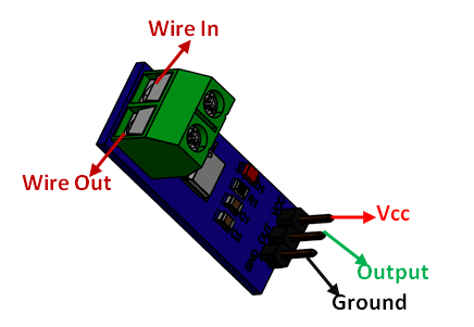
Acs712 Current Sensor Module Pinout Specifications Circuit Datasheet
Precision Current Sensing And Monitoring Circuit Using Ic Ncs21xr Homemade Circuit Projects

Relay Current Flow Wiring Diagrams Youtube
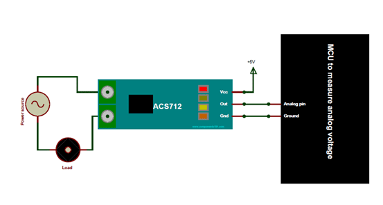
Acs712 Current Sensor Module Pinout Specifications Circuit Datasheet
Current Measurement Ammeter Circuit Pic16f84 Acs712 Electronics Projects Circuits

Fundamentals Of Electrical Relays Working Of Protection Relays
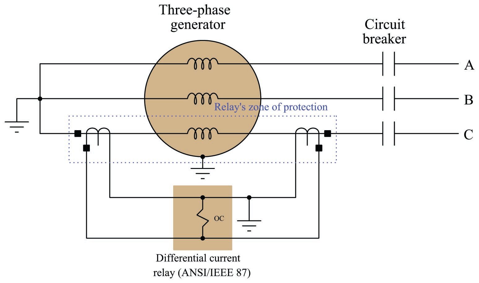
Differential 87 Current Protection Electric Power Measurement And Control Systems Automation Textbook
Using Smart Relay Drivers For Smart Meters Part 1 Industrial Technical Articles Ti E2e Support Forums
Kia Niro Battery Current Sensor Schematic Diagrams High Voltage Battery Control System

New Automatic Load Sensing Power Switch Electronic Circuits Diagram

Refrigerator Current Relay Refrigerator Troubleshooting Diagram

Can I Use The Sim100 To Tell Whether A Bulb Is Burnt Out Print View

Control Relay What Is A Control Relay

Basic Principle Of Relay Operation Electrical Concepts
Current Sensor Amplifier Over Current Switch Electronics Lab Com

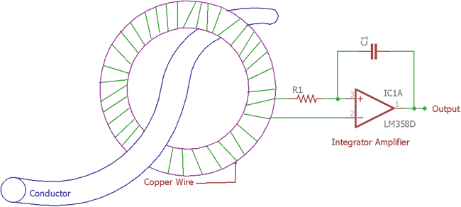
Inductive Non Contact Current Sensor Circuit
3 Phase Monitoring Relay Spdt Phase Failure Undervoltage Overvoltage Ato Com

Current Sensing Transformer Donut Module Very Simple Arduino Project Youtube
0 Response to "42 current sensing relay circuit diagram"
Post a Comment